Method for controlling a lifting device
a technology of lifting device and control method, which is applied in the direction of control device for conveyors, trolley cranes, conveyor parts, etc., can solve the problems of high physical stress, delay in the manipulation process, and relatively time-consuming simulation and subsequent iteration
- Summary
- Abstract
- Description
- Claims
- Application Information
AI Technical Summary
Benefits of technology
Problems solved by technology
Method used
Image


Examples
Embodiment Construction
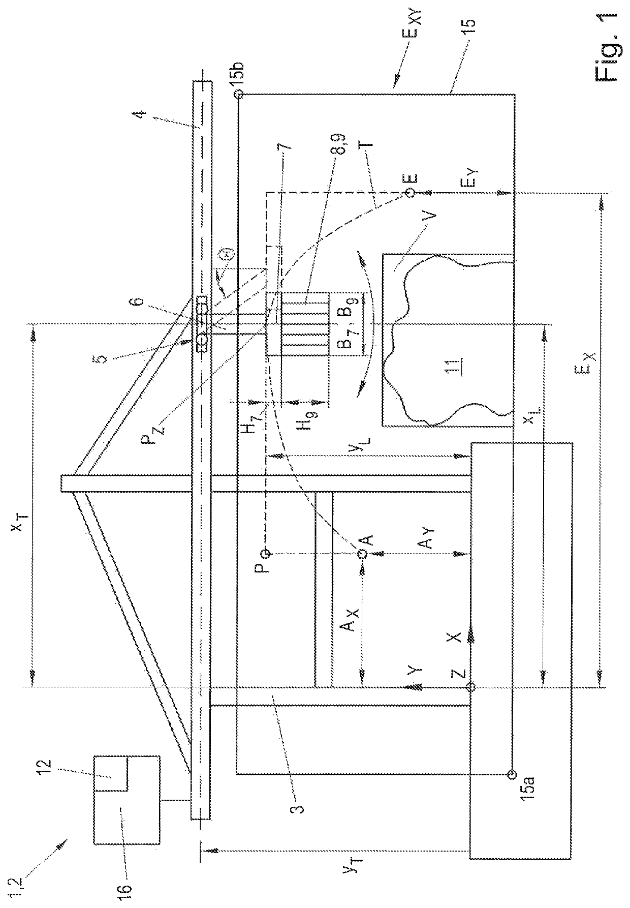
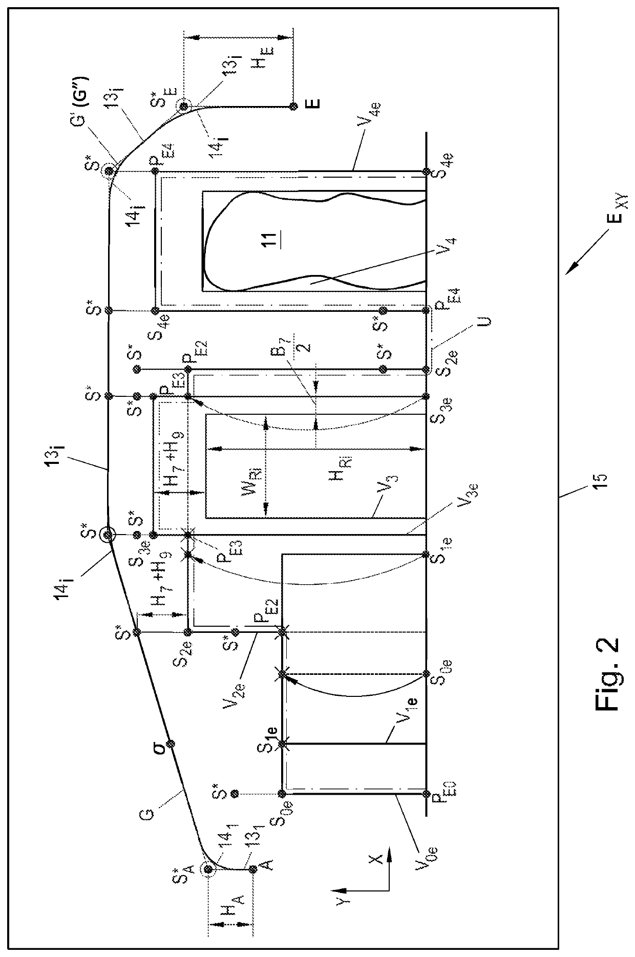
[0007]Embodiments of the invention provide a method for controlling a lifting device that makes it possible to move the load between two points efficiently and in an automated and collision-free manner.
[0008]According to embodiments, kinematic and geometric limits of the lifting device are predetermined, from which the computing unit, based on the geometric or rounded geometric or smooth geometric path, calculates a dynamic or rounded dynamic or smooth dynamic path which provides the time information for moving the load along the geometric or rounded geometric or smooth geometric path, and the geometric or rounded geometric or smooth geometric path and the dynamic or rounded dynamic or smooth dynamic path are combined for producing the trajectory. Furthermore, embodiments are directed to a lifting device with at least two motion axes for moving a load along a trajectory. By this method it is possible that no manual contribution for example from a crane operator is needed any longer ...
PUM
 Abstract
Description
Claims
Application Information
 - R&D
- Intellectual Property
- Life Sciences
- Materials
- Tech Scout
- Unparalleled Data Quality
- Higher Quality Content
- 60% Fewer Hallucinations
Browse by: Latest US Patents, China's latest patents, Technical Efficacy Thesaurus, Application Domain, Technology Topic, Popular Technical Reports.
© 2025 PatSnap. All rights reserved.Legal|Privacy policy|Modern Slavery Act Transparency Statement|Sitemap|About US| Contact US: help@patsnap.com