Backup actuation control unit for controlling an actuator dedicated to a given surface and method of using same

a technology of actuators and control units, applied in the field of aircraft systems, can solve the problems of large effort required to ensure the independence and dissimilarity of backup paths, and the ability to adapt backups, and achieve the effects of reducing maintenance costs, saving wire weight, and simplifying obsolescence managemen

Active Publication Date: 2020-12-15
THALES CANADA INC
View PDF12 Cites 2 Cited by
  • Summary
  • Abstract
  • Description
  • Claims
  • Application Information

AI Technical Summary

Benefits of technology

[0019]For instance, a first advantage of the backup actuation control unit disclosed herein is that it facilitates the certification effort associated therewith. As a matter of fact, as part of the system certification, a demonstration of dissimilarity between the Primary and the backup actuation control unit must be made and rigorously substantiated. The skilled addressee will appreciate that such demonstration covers several level of dissimilarity: components, functional, and architectural. Thanks to its lean design, the backup actuation control unit can be easily compared with its complicated Primary Actuation Control Unit counterpart. It will be appreciated by the skilled addressee that carefully assessing all aspects of a light design with those of a complicated design is much less demanding than comparing two complicated units.
[0020]A second advantage of the backup actuation control unit disclosed herein is that it has a simplified obsolescence management compared to prior-art backup actuation control units. As a matter of fact, the demonstration of dissimilarity must be maintained over the complete product lifecycle. Because the backup actuation control unit comprises only a few components, it is less prone to occurrences of component obsolescence and requires less analysis upon replacement of obsolescent parts.
[0021]A third advantage of the backup actuation control unit disclosed herein is that it helps saving wire weight, which is of great advantage in the aerospace industry. In the industry, the primary actuation control units are sometimes installed close to the actuator to minimize the wiring weight. However, this feature is currently not applied to the actual electronic units performing the backup actuation servo-control functionality. Because it is intended to control a single actuator, the proposed backup actuation control unit can be distributed through the aircraft and located close to their actuator.
[0024]A sixth advantage of the backup actuation control unit disclosed herein is that it has a flexible engagement logic. Because of its distributed topology and straightforward engagement logic depending only on the primary actuation control units sharing the same surface and one flight control computer, the backup actuation control units can be easily engaged per: surface, axis, or aircraft. Implementing such flexible engagement scheme in a centralized backup actuation control unit would require additional electronics to manage the various engagement discrete signals from the primary actuation control units.
[0025]A seventh advantage of the backup actuation control unit disclosed herein is that it offers a compatibility with all current flight controls architecture. Because it is intended to control any single actuator equipped with an hydraulic servo-valve, the backup actuation control unit disclosed herein may be used in any current flight control architecture as they all include enough of the widely used electro-hydraulic servo-controlled actuators.

Problems solved by technology

One drawback of the prior art is the large effort required to guarantee the independence and the dissimilarity of the backup path with respect to the main control paths over the entire aircraft lifecycle.
Another limitation is the ability to adapt the backup means to the size of the aircraft, i.e., tailor the backup means according to the number, type, and location of the aircraft actuators.

Method used


Image

  • Backup actuation control unit for controlling an actuator dedicated to a given surface and method of using same
  • Backup actuation control unit for controlling an actuator dedicated to a given surface and method of using same
  • Backup actuation control unit for controlling an actuator dedicated to a given surface and method of using same

Examples


first embodiment

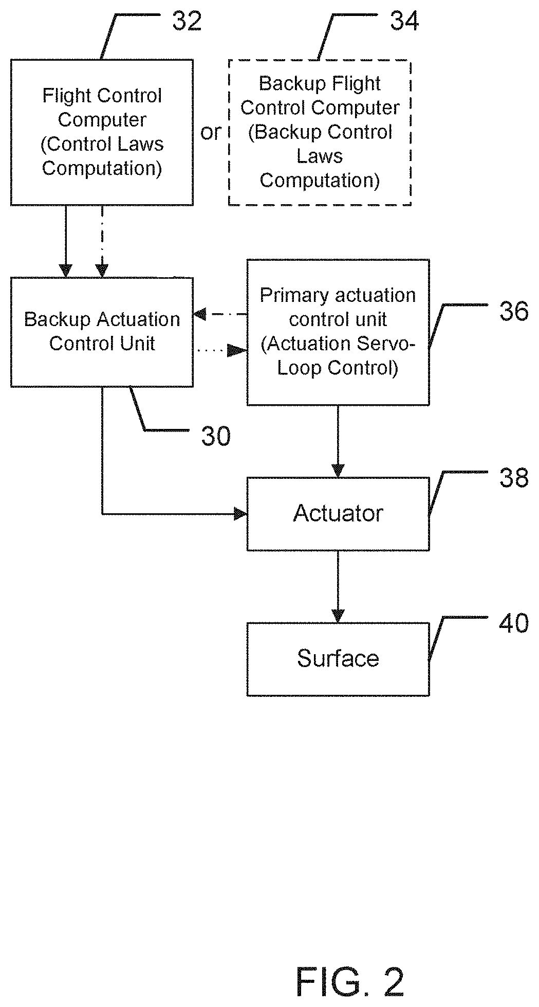
[0064]Now referring to FIG. 2, there is shown a system in which a backup actuation control unit is used.

[0065]In this first embodiment, the backup actuation control unit 30 is operatively connected to a flight control computer 32 or to a backup flight control computer 34. More precisely, the backup actuation control unit 30 receives a surface position command signal and an engagement signal from the flight control computer 32.

[0066]The backup actuation control unit 30 is operatively connected to a primary actuation control unit 136. More precisely, the backup actuation control unit 30 receives an engagement signal from the primary actuation control unit 136. The backup actuation control unit 30 further provides a reporting signal to the primary actuation control unit 136.

[0067]The primary actuation control unit 136 is operatively connected to the actuator 38. More precisely, the primary actuation control unit 136 provides a command signal to the actuator 38.

[0068]The actuator 38 is ...

second embodiment

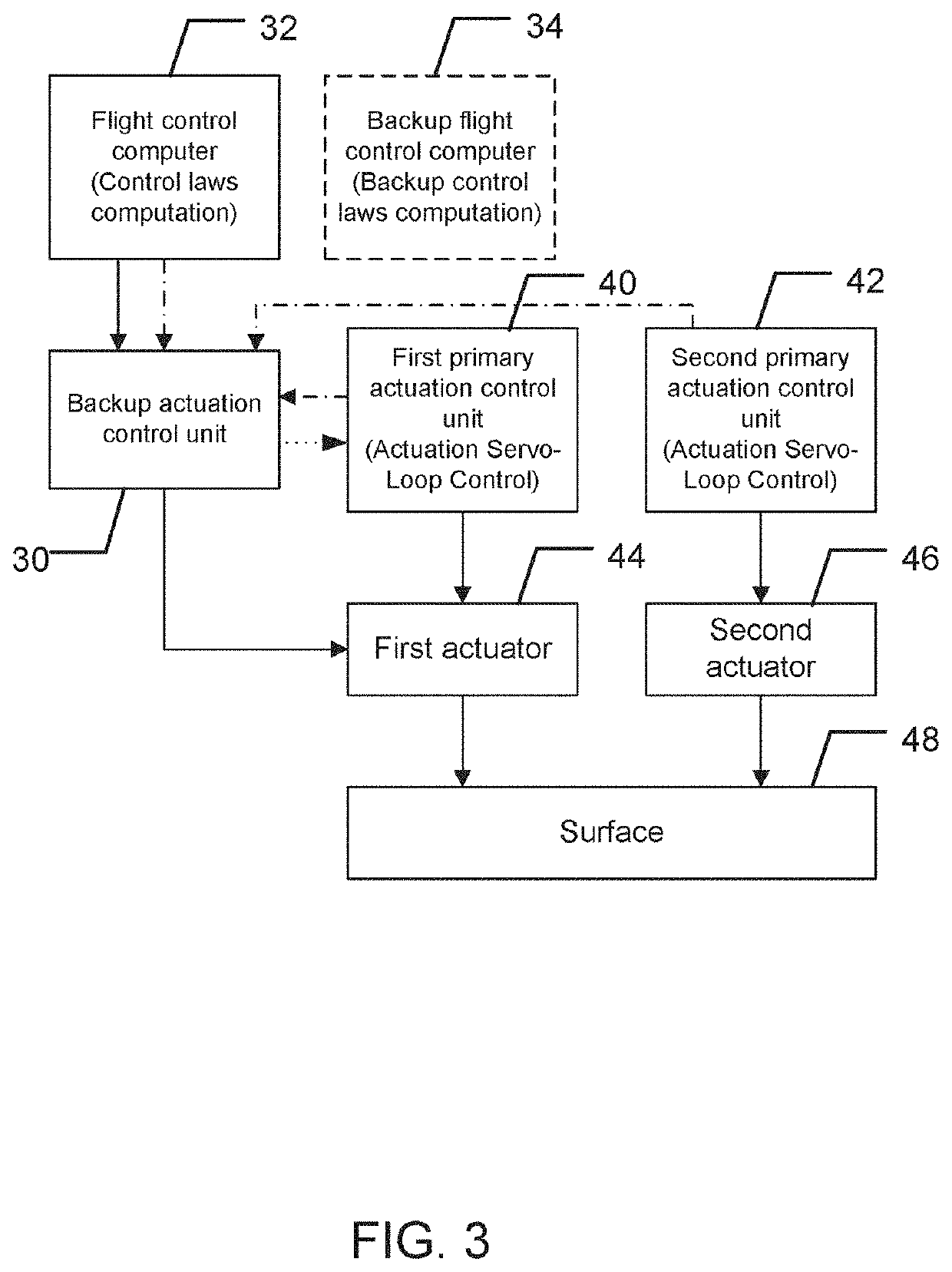
[0070]Now referring to FIG. 3, there is shown a second embodiment in which a backup actuation control unit is used.

[0071]In this second embodiment, the backup actuation control unit 30 is operatively connected to the flight control computer 32 or the backup flight control computer 34. More precisely, the backup actuation control unit 30 receives a surface position command signal and an engagement signal from the flight control computer 32.

[0072]The backup actuation control unit 30 is operatively connected to a first primary actuation control unit 40 and also to a second primary actuation control unit 42. More precisely, the backup actuation control unit 30 receives a primary actuation engagement signal from the first primary actuation control unit 40. The backup actuation control unit 30 receives an engagement signal from the second primary actuation control unit 42. The backup actuation control unit 30 further provides a reporting signal to the first primary actuation control unit ...

third embodiment

[0078]Now referring to FIG. 4, there is shown a third embodiment in which a backup actuation control unit is used.

[0079]In this third embodiment, the backup actuation control unit 30 is operatively connected to the flight control computer 32 or to the backup flight control computer 34. More precisely, the backup actuation control unit 30 receives a surface position command signal and an engagement signal from the flight control computer 32.

[0080]The backup actuation control unit 30 is operatively connected to a first primary actuation control unit 50, to a second primary actuation control unit 52 and to a third primary actuation control unit 54. More precisely, the backup actuation control unit 30 receives a first primary actuation control unit engagement signal from the first primary actuation control unit 50. The backup actuation control unit 30 receives a second primary actuation control unit engagement signal from the second primary actuation control unit 52. The backup actuatio...


PUM


Abstract

A backup actuation control unit for controlling an actuator dedicated to a given surface. The backup actuation control unit comprises a processing unit operatively connected to one of a flight control computer and a backup flight control computer, to an actuator used for actuating a given surface and to at least one primary actuation control unit, each of the at least one primary actuation control unit for controlling a corresponding actuator used for actuating the given surface, wherein the processing unit receives a surface position command signal from one of the flight control computer and the backup flight control computer and an actuator position signal received from the actuator and provides a corresponding command signal to the actuator if an engagement signal is received from the flight control computer or the backup flight control computer and from the at least one primary actuation control unit.

Description

CROSS-REFERENCE TO RELATED APPLICATION[0001]The present patent application claims priority on U.S. Patent Application No. 62 / 453,206, filed on Feb. 1, 2017.FIELD[0002]The invention relates to aircraft systems. More precisely, the invention pertains to a backup actuation control unit for controlling an actuator dedicated to a given surface and to a method of using same.BACKGROUND[0003]Flight control systems are among the most critical systems on the aircraft. They must achieve both a high integrity and a high availability. Consequently, every flight control system must include backup or reversionary paths to be certifiable. These backup paths parallel the main control paths from which they must be independent and dissimilar.[0004]One drawback of the prior art is the large effort required to guarantee the independence and the dissimilarity of the backup path with respect to the main control paths over the entire aircraft lifecycle. Another limitation is the ability to adapt the backup...

Claims


Application Information

Patent Timeline
Patent Type & Authority Patents(United States)
IPC IPC(8): B64C13/50G05D1/08
CPCB64C13/505B64C13/503G05D1/0808G05D1/0077
Inventor CADOTTE, PATRICKCLEMENT, FREDERICKBIRENBAUM, NICOLASVASILIU, CATALINCHAN TAVE, ERIC
Owner THALES CANADA INC
Why Eureka
Try Eureka