Power line communication device, in-vehicle device and in-vehicle system
a technology of in-vehicle device and communication device, which is applied in the direction of transmission/receiving by adding signal to wave, power distribution line transmission, transportation and packaging, etc., can solve the problems of increasing manufacturing cost of automobiles and fuel consumption deterioration, so as to reduce loss, reduce component costs, and reduce loss.
- Summary
- Abstract
- Description
- Claims
- Application Information
AI Technical Summary
Benefits of technology
Problems solved by technology
Method used
Image
Examples
first embodiment
[0024]
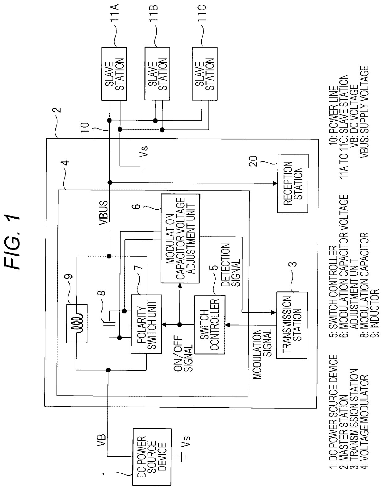
[0025]First, an in-vehicle system will be described using an automobile as an example. FIG. 9 is a diagram illustrating a configuration of the in-vehicle system according to a first embodiment. In FIG. 9, reference numeral 70 denotes an ECU (in-vehicle device) mounted on an automobile 80, 71A to 71C denote actuators, and 72 denotes a battery. Although a large number of sensors and actuators are mounted on the automobile 80, FIG. 9 illustrates only three actuators 71A to 71C among these sensors as representatives. The battery 72 is connected to the ECU 70 by a power source line 73, and is a DC power source that supplies power to the ECU 70 using a battery voltage as a power source voltage.
[0026]The ECU 70 is connected to the actuators 71A to 71C by a power line 10. In the drawing, the power line 10 is drawn as one line, but is configured by a pair of two wires. The ECU 70 supplies a DC voltage supplied from the battery 72 to the actuators 71A to 71C via the power line 10. Altho...
second embodiment
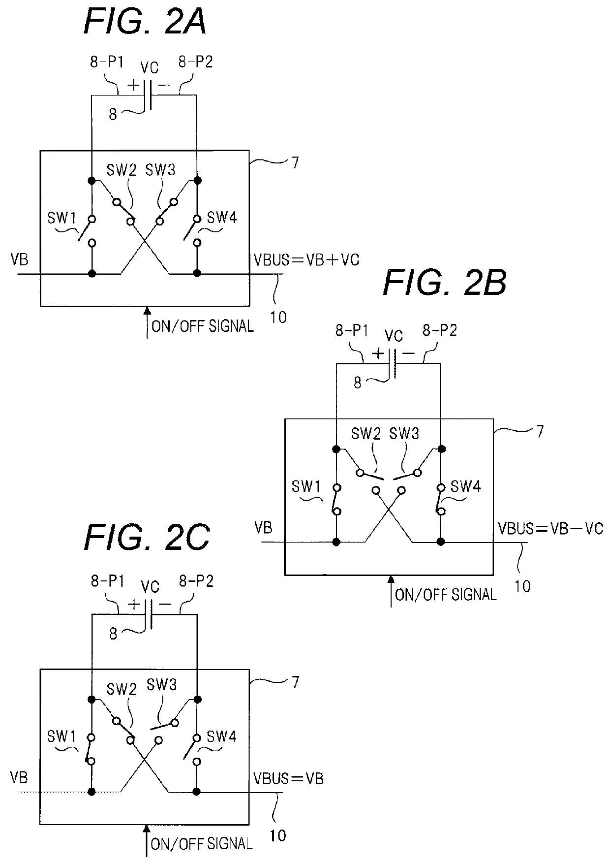
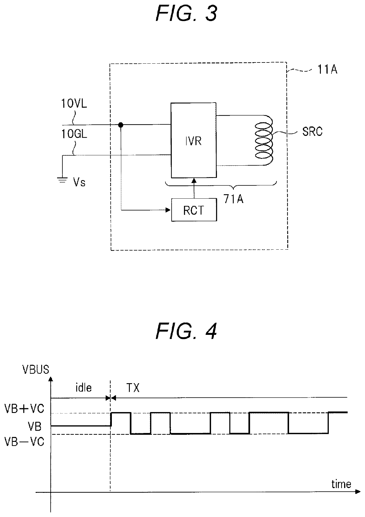
[0070]In the first embodiment, the charging of the modulation capacitor 8 is performed during a period when transmission is not performed (for example, the idle period idle), but it is desirable that the charging be performed during the transmission period to stabilize the holding voltage of the modulation capacitor 8. In the voltage fluctuation during the transmission period TX (FIG. 4) and / or transmission during a long transmission period, for example, the charge held in the modulation capacitor 8 decreases, and the modulation amplitude voltage VC which is the holding voltage of the modulation capacitor 8 becomes unstable. Therefore, it is desirable to stabilize the holding voltage of the modulation capacitor 8 even during the transmission period.
[0071]The second embodiment provides a technique for stabilizing the holding voltage of the modulation capacitor 8 even during the transmission period. FIG. 5 is a block diagram illustrating a configuration of a main part of a master stat...
third embodiment
[0092]As described in FIG. 6, the modulation capacitor voltage adjustment unit 6 can discharge the modulation capacitor 8 when modulating the supply voltage VBUS to the H level, and can charge the modulation capacitor 8 when modulating the supply voltage VBUS to the L level. In this case, the time during which the modulation capacitor 8 is charged or discharged depends on the time of the charge signal chg and the discharge signal dhg output from the voltage comparator 61 and the period during which the supply voltage VBUS is at the L level and the H level. That is, by adjusting not only the charge or discharge instruction (charge signal or discharge signal) for the modulation capacitor 8 by the modulation capacitor voltage adjustment unit 6, but also the period when the supply voltage VBUS is at the H level and the period when the supply voltage VBUS is at the L level, the adjustment can adjust the holding voltage of the modulation capacitor 8.
[0093]In other words, by extending the ...
PUM
 Abstract
Description
Claims
Application Information
 - R&D
- Intellectual Property
- Life Sciences
- Materials
- Tech Scout
- Unparalleled Data Quality
- Higher Quality Content
- 60% Fewer Hallucinations
Browse by: Latest US Patents, China's latest patents, Technical Efficacy Thesaurus, Application Domain, Technology Topic, Popular Technical Reports.
© 2025 PatSnap. All rights reserved.Legal|Privacy policy|Modern Slavery Act Transparency Statement|Sitemap|About US| Contact US: help@patsnap.com


