Cooling system for an internal combustion engine

a cooling system and internal combustion engine technology, applied in the direction of engine cooling apparatus, liquid cooling, cylinders, etc., can solve the problems of relative long heating-up times of the coolant, jackets have a disadvantageous effect on the coolant volume, etc., to achieve short heating-up times, low coolant volume, and advantageous effect on the heating-up time of the coolan

Active Publication Date: 2020-12-08
AVL LIST GMBH
View PDF35 Cites 1 Cited by
  • Summary
  • Abstract
  • Description
  • Claims
  • Application Information

AI Technical Summary

Benefits of technology

[0009]Since the flow occurs through the first cooling jacket in the transverse direction of the internal combustion engine, it is possible to avoid external lines between the first and the second cooling jacket on the one hand and the cross-section of the first cooling jacket, as seen normally to the crankshaft axis, can be kept at a low dimension, as a result of which the coolant volume can be reduced drastically. The second cooling jacket is activated or deactivated as required, wherein the full coolant quantity always flows through the first cooling jacket of the cylinder head. As a result, a sufficient removal of heat from thermally highly loaded regions around the exhaust valves in the fire deck can be ensured in every operating range of the internal combustion engine.
[0010]The collecting chamber for the coolant can be integrated in the cylinder block according to a first embodiment of the invention. The collecting chamber is hydraulically separated from the second cooling jacket within the cylinder block. This variant offers the advantage that no constructional measures need to be taken for housing the collecting chamber in the cylinder head, which simplifies the production of the cylinder head.
[0011]It is provided in a second embodiment of the invention that the collecting chamber is arranged in the cylinder head, wherein preferably the collecting chamber is arranged between the exhaust ports and the cylinder-head sealing surface. This arrangement offers the advantage that as a result of the collecting chamber integrated in the cylinder head the exhaust ports, and optionally also an exhaust manifold integrated in the cylinder head, can additionally be cooled.
[0013]In order to enable an adequate transport of heat from thermally critical regions of the cylinder head in any operating range and rapid heating after cold starting, it is advantageous if the first coolant outlet of the cylinder head has a continuous flow connection with the return line of the cooling system and the second coolant outlet of the cylinder head is switchably connected via the first valve to a return line of the cooling system.
[0017]It can be provided in a further embodiment of the invention that the coolant pump is driven by a camshaft preferably arranged in the cylinder head. This measure offers the advantage that the coolant volume between the coolant pump and the first cooling jacket can be reduced to a minimum, which has an advantageous effect on the heating-up time of the coolant.
[0018]An especially low coolant volume and thus very short heating-up times can be achieved when the coolant inlet, the first coolant outlet and the second coolant outlet are arranged in the cylinder head.

Problems solved by technology

The disadvantage of relatively long heating-up times of the coolant is caused by the necessary relatively large coolant volume.
Said longitudinal flow as well as a relatively large number of required external lines between the cylinder head water jacket the cylinder block water jacket have a disadvantageous effect on the coolant volume.

Method used


Image

  • Cooling system for an internal combustion engine
  • Cooling system for an internal combustion engine
  • Cooling system for an internal combustion engine

Examples


first embodiment (fig.1 to fig.9)

First Embodiment (FIG. 1 to FIG. 9)

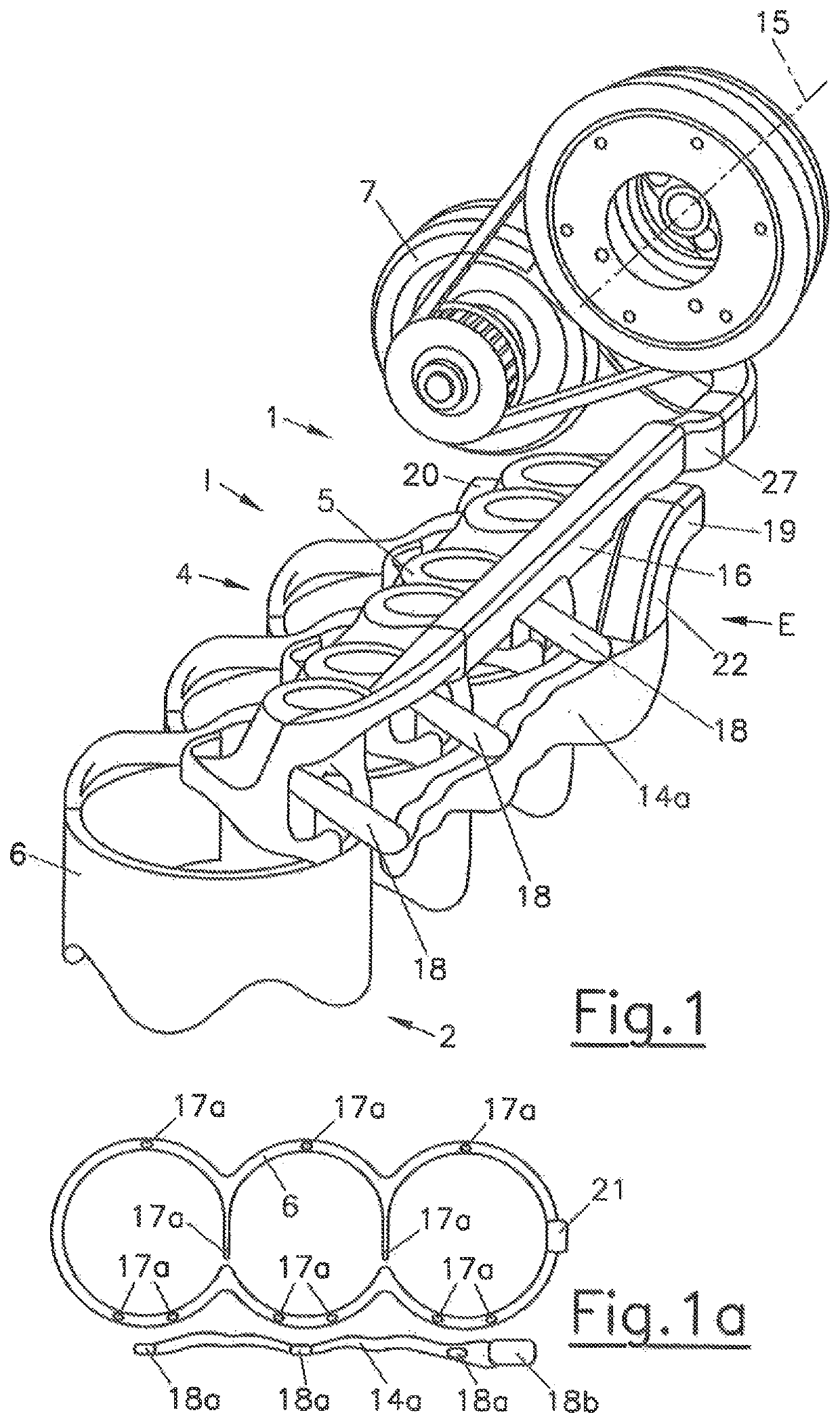
[0051]In the first switching position of the cooling system 4 shown in FIG. 4, the first valve 8 and the second valve 9 are in a first valve position, wherein the first switching positions are assigned to the cold state of the coolant. The coolant is conveyed by the first coolant pump 7 to the first cooling jacket 5 of the cylinder head 1. The first coolant outlet 19 is connected to the valve outlet 8c of the first thermostat valve 8 in the first valve position of the first valve 8, but the second coolant outlet 20 is separated from the valve outlet 8c of the first valve 8. As a result of the blocked discharge from the second cooling jacket 6, the coolant is unable to transfer from the first cooling jacket 5 to the second cooling jacket 6, as a result of which the coolant only flows through the first cooling jacket 5 in the cylinder head 1. The entire coolant moves from the first cooling jacket 5 via the collecting ports 18 to the collecting chambe...

second embodiment (fig.10 to fig.17)

Second Embodiment (FIG. 10 to FIG. 17)

[0054]This embodiment differs from the first embodiment shown in FIG. 1 to FIG. 9 in such a way that the collecting chamber 14b is now not arranged in the cylinder block 2 but in the cylinder head 1. This offers the advantage that the coolant volume can be reduced further and the cylinder block 2 can be arranged with a simpler configuration. As is shown in FIG. 10a, substantially fewer openings 17a are required in the cylinder-head sealing surface 28.

[0055]FIGS. 12 and 13 show a first switching position of the cooling system 4 for the second embodiment, wherein the first valve 8 and the second valve 9 are each situated in the first valve position, wherein the first valve positions are associated with the cold internal combustion engine or the cold cooling liquid. The coolant flows from the coolant pump 7 to the distributor chamber 16 and further into the first cooling jacket 5 of the cylinder head 1, with the coolant flowing through the same in ...


PUM


Abstract

The invention relates to a cooling system (4) for an internal combustion engine having at least one cylinder head (1), the at least one cylinder head being connected to at least one cylinder block (2) by means of a cylinder-bead sealing surface (28). The cooling system comprises at least one first cooling jacket (5) arranged in the cylinder head (1), the at least one first cooling jacket having a flow connection to at least one coolant inlet (27) and at least one first coolant outlet (19), and at least one second cooling jacket (6) arranged in the cylinder block (2), the at least one second cooling jacket being connected to at least one second coolant outlet (20) in the cylinder head (1), wherein the first cooling jacket (5) and the second cooling jacket (6) are connected to each other by means of at least one connection flow path (17), which preferably extends through an opening (17a) in the cylinder-bead sealing surface (28), and a liquid coolant can flow through the first cooling jacket and the second cooling jacket in succession, and wherein the coolant flow through the second cooling jacket (6) can be controlled by means of at least one first valve (8), preferably a thermostat valve, which blocks the coolant flow through the second cooling jacket (6) in a first valve position and allows the coolant flow through the second cooling jacket in at least one second valve position. In order to enable quick heating of the coolant while achieving optimal cooling of the internal combustion engine, flow through the first cooling jacket (5) according to the invention is possible in a transverse direction of the internal combustion engine.

Description

BACKGROUND OF THE INVENTIONField of the Invention[0001]The invention relates to a cooling system for an internal combustion engine, which includes at least one cylinder head connected to at least one cylinder block by means of at least one cylinder-head sealing surface, at least one first cooling jacket arranged in the cylinder head having a flow connection with at least one coolant inlet and at least one first coolant outlet, and at least one second cooling jacket arranged in the cylinder block which is connected to at least one second coolant outlet, wherein the first and the second cooling jackets are connected to each other by at least one connection flow path which preferably extends through an opening in the cylinder-head sealing surface, and wherein a liquid coolant can flow through the first cooling jacket and the second cooling jacket in succession, and wherein the coolant flow through the second cooling jacket can be controlled by at least one first valve, preferably a the...

Claims


Application Information

Patent Timeline
Patent Type & Authority Patents(United States)
IPC IPC(8): F02F1/36F01P3/02F02F1/40F02F1/10F01P11/16
CPCF02F1/10F02F1/40F01P11/16F01P3/02F01P2003/024F01P2003/028F01P7/16F01P7/165
Inventor BILLER, REINHARDKNOLLMAYR, CHRISTOFFUCKAR, GERNOT
Owner AVL LIST GMBH
Why Eureka
Try Eureka