Connection system for electrically connecting a fixture in a vehicle

a technology for connecting systems and fixtures, applied in the direction of seating arrangements, non-rotary current collectors, coupling device connections, etc., can solve the problems of difficult to realize variable seat distances, and achieve high mechanical stability, prevent tilting, and high tensile strength

Active Publication Date: 2020-12-08
AIRBUS OPERATIONS GMBH
View PDF15 Cites 0 Cited by
  • Summary
  • Abstract
  • Description
  • Claims
  • Application Information

AI Technical Summary

Benefits of technology

[0010]A connection system for electrically connecting a fixture in a vehicle is proposed, the connection system having at least one cable, and a housing with a cable inlet and a cable outlet, and with a receiving space which is formed in the housing and extends helically along a housing axis with a receiving space cross section from the cable inlet towards the cable outlet, wherein the at least one cable has a cable cross section and runs completely through the receiving space from the cable inlet towards the cable outlet, with cable coils being formed, and wherein a radial extent of the cable cross section is smaller than a radial extent of the receiving space cross section, and therefore different lengths of the at least one cable can be accommodated in the receiving space with different coil diameters being formed.
[0017]The functioning principle of the connection system according to the disclosure is based completely on passive components which do not require any movable parts and are therefore virtually maintenance-free. In addition, the connection system according to the disclosure can be operated very easily and intuitively and errors in the handling can be virtually completely prevented because of the very simple configuration. Nevertheless, the function of the connection system is highly robust and reliable, and the latter furthermore has a very low weight.
[0019]As mentioned above, the inner radial boundary surface can have a diameter which corresponds to a minimum bending diameter of the cable or exceeds said bending diameter. By this means, the connection system can prevent damage to the cable due to the latter being wound together excessively strongly. It is therefore not possible to fall short of the bending diameter.
[0023]In a particularly advantageous embodiment, the connection system according to the disclosure has at least one flexurally soft, tension-proof supporting element which surrounds the at least one cable in a circumferentially flush manner and extends over a substantial part of the length of the cable. The supporting element is a protection device which protects the cable from mechanical impairment. By means of the flexurally soft configuration, the supporting element can completely follow the movement of the cable. However, because of the tension-proof design, it is very easily possible to pull the supporting element instead of the cable in order to influence the coil diameter of the cable. In particular in the case of rather thin and more sensitive cables, the integrity thereof can be ensured. In addition, vibrations which occur during the operation of the vehicle cannot lead, because of the enclosing of the cable, to undesirable friction between the cable and boundary surfaces of the receiving space, which can prevent the cable from becoming worn through. For simplified guidance of the supporting element, rollers can be fastened to the housing, the rollers facilitating the sliding of the chain into and out of the housing and at the same time also preventing tilting. The rollers can be arranged at the cable inlet, in particular on the outside directly after the cable inlet.
[0024]The supporting element preferably has a multiplicity of interconnected chain links. The chain links could be produced by way of example from a plastic which has high tensile strength and at the same time generally high mechanical stability. In addition, the chain links can be provided with a surface which has a low coefficient of stiction and which facilitates the pulling of the supporting element or of the cable arranged therein into the receiving space. The chain links in each case encircle an outer circumference of the cable completely and are preferably mounted on one another so as to be pivotable about at least one axis such that the housing axis can be revolved. However, the chain links and the bearings lying in-between are intended to be configured in such a manner that they additionally permit an axial movement of the chain links along the housing axis.

Problems solved by technology

However, it may be difficult to realize variable seat distances without separating connections of cabling during the displacement of passenger seats and subsequently restoring same taking the changed seat distance into consideration.

Method used


Image

  • Connection system for electrically connecting a fixture in a vehicle
  • Connection system for electrically connecting a fixture in a vehicle
  • Connection system for electrically connecting a fixture in a vehicle

Examples


Embodiment Construction

[0035]The following detailed description is merely illustrative in nature and is not intended to limit the embodiments of the subject matter or the application and uses of such embodiments. As used herein, the word “exemplary” means “serving as an example, instance, or illustration.” Any implementation described herein as exemplary is not necessarily to be construed as preferred or advantageous over other implementations. Furthermore, there is no intention to be bound by any expressed or implied theory presented in the preceding technical field, background, brief summary or the following detailed description.

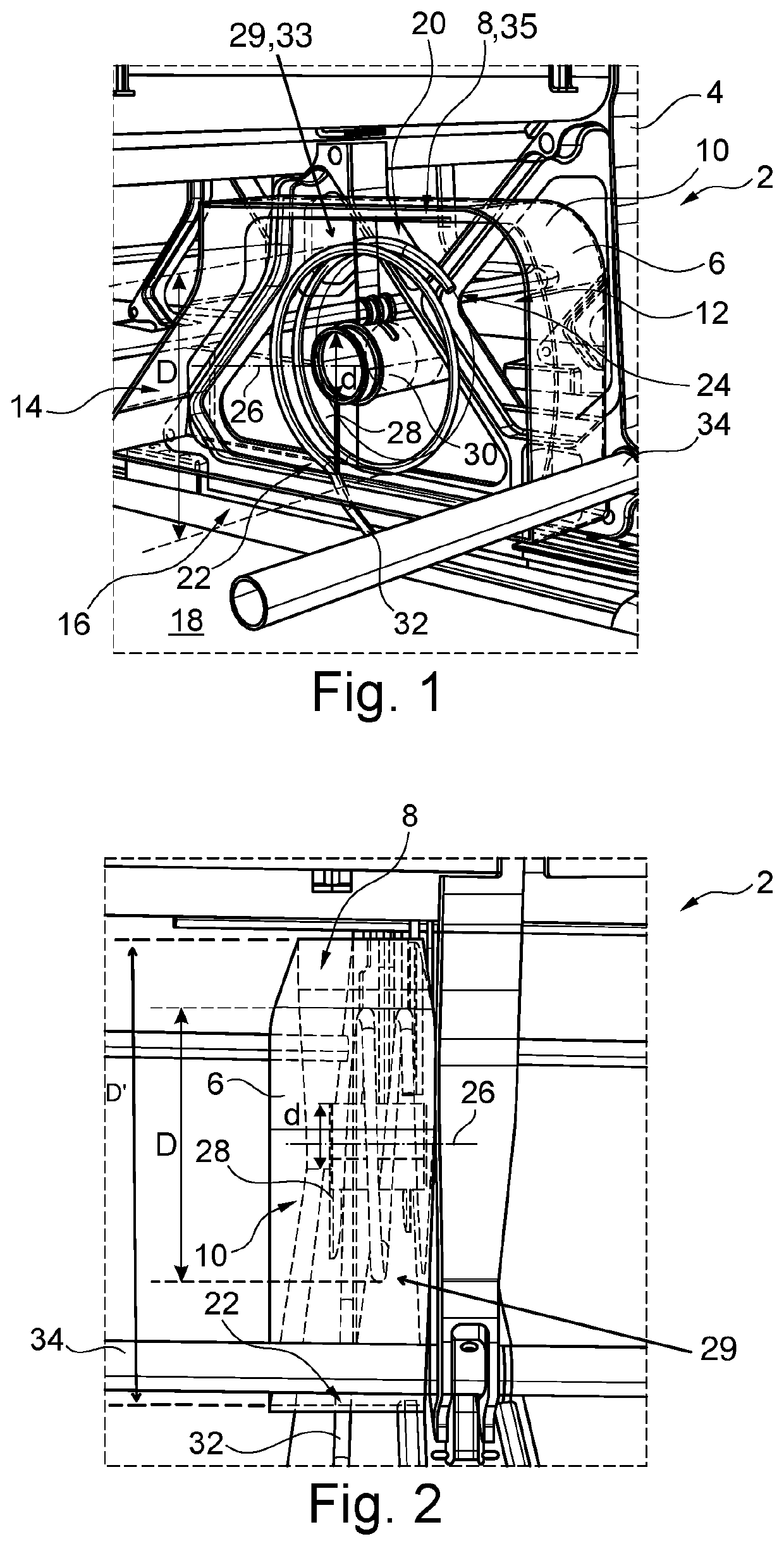
[0036]FIG. 1 shows a connection system 2 for electrically connecting a fixture 4, which is embodied here by way of example as a vehicle seat. The connection system 2 has a housing 6, the shape of which fits harmoniously into an existing construction space of the fixture 4.

[0037]The housing 6 has an interior 8 which is defined by an edge 10 and two covers 12 and 14 running parall...


PUM


Abstract

A connection system for electrically connecting a fixture in a vehicle has at least one cable, and a housing with a cable inlet and a cable outlet, and with a receiving space which is formed in the housing and extends helically along a housing axis with a receiving space cross section from the cable inlet towards the cable outlet. The cable has a cable cross section and runs completely through the receiving space from the cable inlet towards the cable outlet, with cable coils being formed. A radial extent of the cable cross section is smaller than a radial extent of the receiving space cross section. Therefore, different lengths of the at least one cable can be accommodated in the receiving space with different coil diameters being formed.

Description

CROSS-REFERENCE TO PRIORITY APPLICATION[0001]This application claims the benefit of, and priority to, German patent application number DE 102018115560.3, filed Jun. 28, 2018. The content of the referenced application is incorporated by reference herein.TECHNICAL FIELD[0002]Embodiments of the subject matter described herein relate generally to a connection system for electrically connecting a fixture in a vehicle, to a passenger seat system for a vehicle, and to an aircraft with an aircraft fuselage, a cabin formed in the latter, and at least one passenger seat system arranged in the cabin.BACKGROUND[0003]In many modern means of transport, for example commercial aircraft, electronic entertainment systems and other systems are arranged on passenger seats. Said systems require electric lines in order to be able to produce a connection to corresponding power and data sources on board the means of transport. For this purpose, in particular seat-to-seat cabling is used. In this case, powe...

Claims


Application Information

Patent Timeline
Patent Type & Authority Patents(United States)
IPC IPC(8): H01R39/00H01R13/72H01R41/00B64D11/06H01R13/66B64C1/18H02G3/38H01R13/60
CPCH02G3/383B64C1/18B64D11/0624B64D2221/00B65H75/425H02G11/02B64C1/20H02G11/006
Inventor FUERSTENBERG, MALTESCHWENK, SERGEJRISTOW, RAINERSCHOMAKER, LARSSCHULZ, ALEXANDER
Owner AIRBUS OPERATIONS GMBH
Why Eureka
Try Eureka