Apparatus and method for selective disabling of LiDAR detector array elements

a detector array and selective disassembly technology, applied in the field of optical signal processing, can solve the problems of requiring precise alignment, mechanical parts that are prone to failure, and cannot isolate multi-path reflections, and the detection resolution is limited to the array resolution

Active Publication Date: 2020-11-17
QUANERGY SOLUTIONS INC
View PDF13 Cites 0 Cited by
  • Summary
  • Abstract
  • Description
  • Claims
  • Application Information

AI Technical Summary

Problems solved by technology

The major drawbacks to these systems are that they require precise alignment and have mechanical parts that are prone to failure.
Because of the requirement that the detector can observe a large field-of-view, a number of new issues emerge.
Limitations of this approach are that multi-path reflections cannot be isolated, which means false positive detection events are likely, the detection resolution is limited to the array resolution, and that every pixel in the sensor has to be processed fully since no information is known about the emission pattern and the scene beforehand.
A hybrid Flash / Scanning system can help since the detection field-of-view is narrowed, but the drawbacks of scanning LiDAR systems persist.
There are challenges with implementing this approach in optical wavelengths that can lead to limitations on the overall LiDAR system.

Method used


Image

  • Apparatus and method for selective disabling of LiDAR detector array elements
  • Apparatus and method for selective disabling of LiDAR detector array elements
  • Apparatus and method for selective disabling of LiDAR detector array elements

Examples


Embodiment Construction

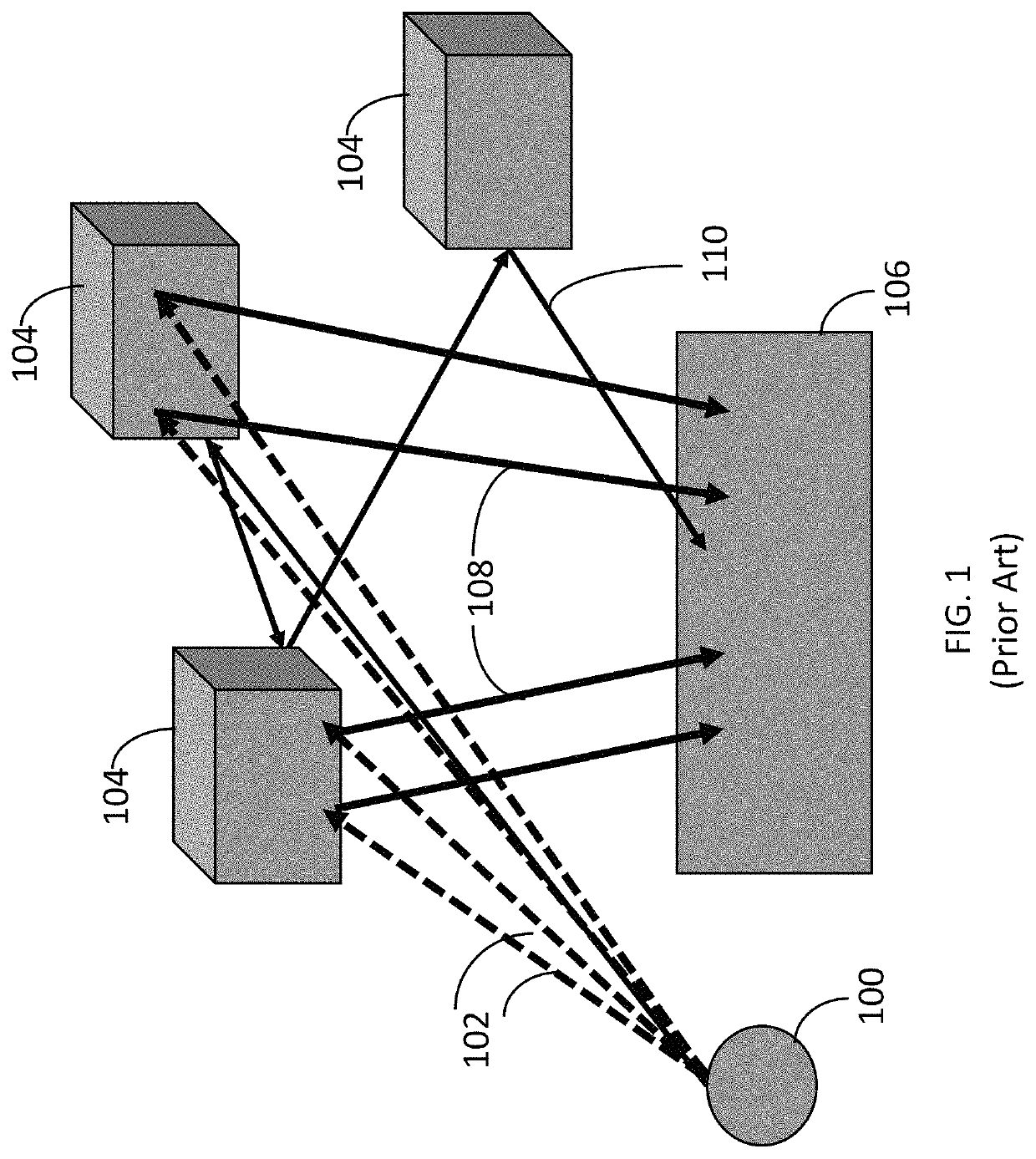
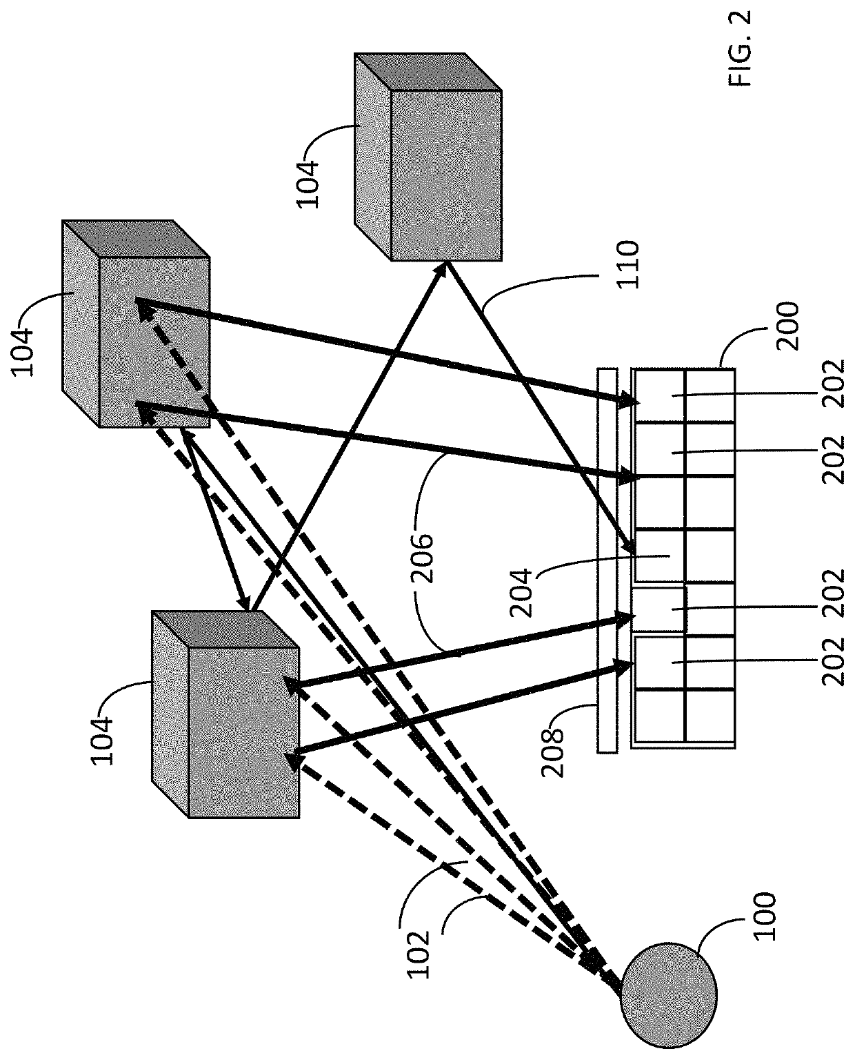
[0017]FIG. 2 illustrates a LiDAR detector array 200 configured in accordance with an embodiment of the invention. The LiDAR detector array 200 includes individual elements 202 that are selectively enabled to collect expected return signals 206 and individual elements 204 that are disabled if they are in a position that does not correspond to an expected return path. Thus, in this example, element 204 is disabled and therefore does not process multi-path interference signal 110. The detector array 200 may have an associated optical system 208 to focus optical energy on the detector array 200. In one embodiment, the optical system 208 includes individually addressable optical elements to focus or defocus optical energy onto the detector array to improve signal-to-noise ratio.

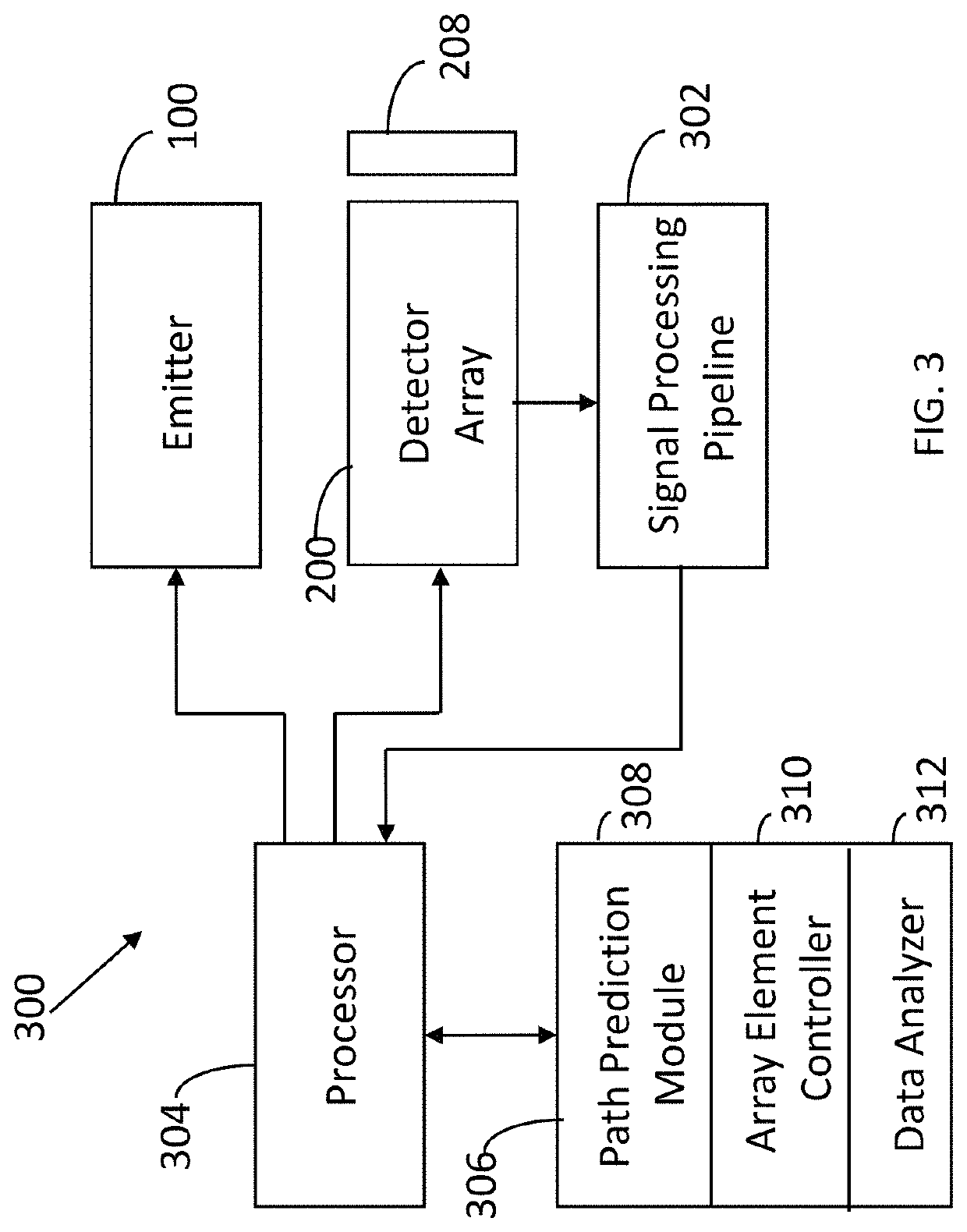
[0018]FIG. 3 illustrates a system 300 with electronic components to implement an embodiment of the invention. The system 300 includes the emitter 100, detector array 200 and optical system 208. Signals from the de...


PUM


Abstract

An apparatus has a beam steerable laser emitter and a detector array with array elements. Electronics selectively enable first array elements corresponding to expected return signal paths and disable second array elements corresponding to unexpected return signal paths.

Description

FIELD OF THE INVENTION[0001]This invention relates generally to optical signal processing. More particularly, this invention relates to techniques for selectively disabling LiDAR detector array elements to reduce multi-path interference and improve signal-to-noise ratio.BACKGROUND OF THE INVENTION[0002]In traditional laser ranging systems a laser source is paired with a detector array or point detector such that the reflected signals returning from the object being interrogated will fall on the detector array or point detector. The detector array may comprise, for example, Avalanche Photodiodes (APDs), PIN (p-type, intrinsic, n-type) photodiodes, Silicon Photomultipliers (SiPMs), or Single-Photon Avalanche Diodes (SPADs). For three-dimensional (3-D) sensing and mapping applications using this configuration, the laser and detector array are synchronously scanned across the scene by either mechanically rotating the laser and detector array or using a spinning mirror to sweep the laser...

Claims


Application Information

Patent Timeline
Patent Type & Authority Patents(United States)
IPC IPC(8): G01S7/00G01S7/481G01S17/32G01S7/4914G01S7/4863G01S17/42
CPCG01S7/4863G01S17/32G01S7/4914G01S17/42G01S7/4811
Inventor FIELD, RYANIZUHARA, TOMOYUKIELDADA, LOUAY
Owner QUANERGY SOLUTIONS INC
Why Eureka
Try Eureka