Containment systems for sealing a pass-through in a well, and methods therefore
a technology for containment systems and pass-throughs, applied in the field of wellheads, can solve problems such as ineffectiveness, and achieve the effects of reducing complications during installation, facilitating orientation and alignment, and facilitating installation
- Summary
- Abstract
- Description
- Claims
- Application Information
AI Technical Summary
Benefits of technology
Problems solved by technology
Method used
Image
Examples
first embodiment
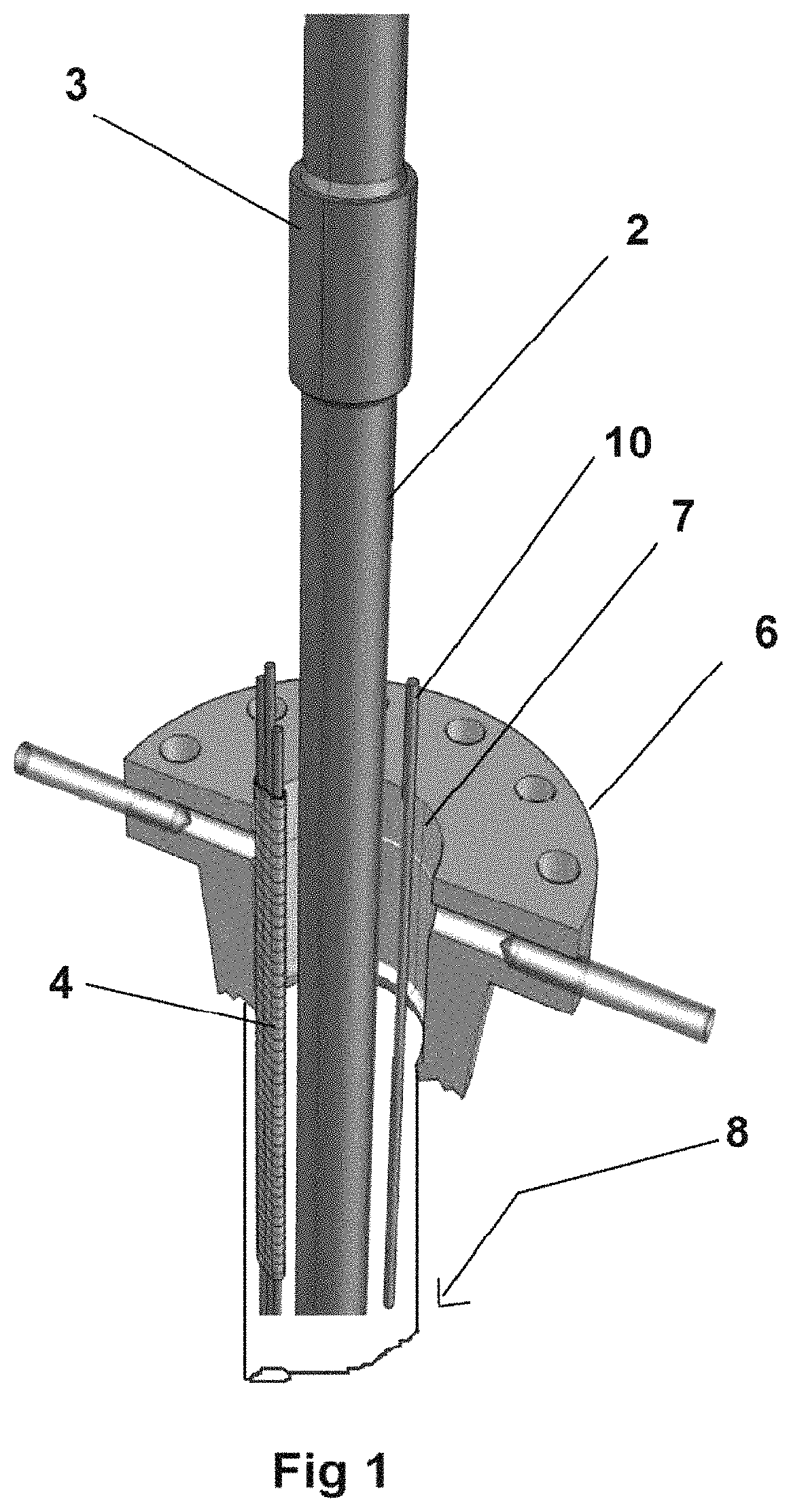
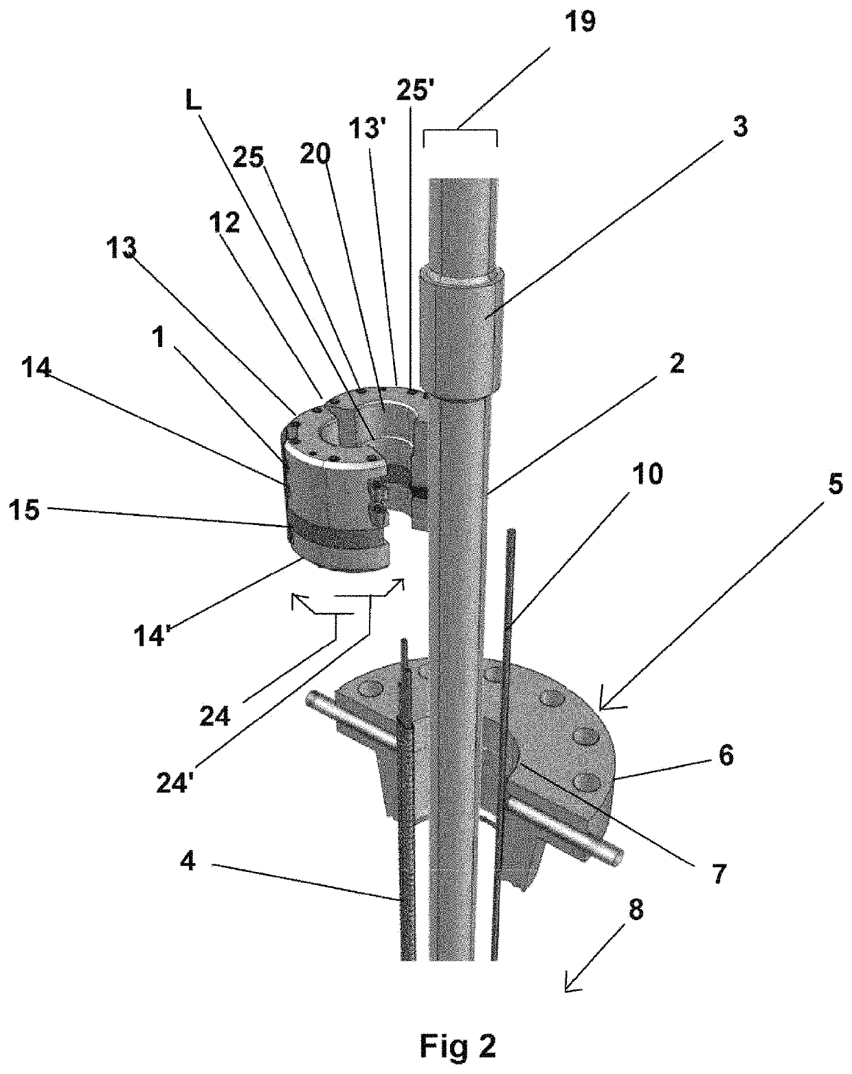
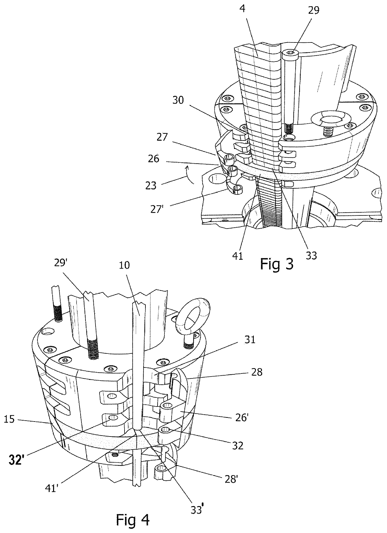
[0095]Continuing with FIGS. 2-9, the present invention comprises a system to provide on a temporary or short-term basis a pass-through seal of a wellhead having components comprising a split, wrap-around hanger 1 formed of first 13 and second 13′ hanger sections hinged 12 on one side to pivot from open 24 to closed 24′ positions forming hanger 1, the opening of same allowing the positioning of said sections about tubing 2 to envelope same. Each hanger component 13, 13′ comprises an upper 14 and lower 14′ opposing hanger bodies formed of steel or the like (the lower 14′ hanger body may alternatively be referred to as the base plate), and with a main seal 15 of synthetic rubber or other elastomeric compound or the like situated therebetween. Bolts 25, 25′ threadingly engage upper 14 and lower 14′ hanger bodies, passing through seal 15 (via bolt passages formed therethrough, joining same).
[0096]The first 13 and second 13′ hanger components forming hanger 1, forms a receiver which is fo...
second embodiment
[0111]the invention provides a permanent or long-term pass-through hanger system for sealing a well having components such as ESP power cables, capillary lines, or like emanating therefrom.
[0112]Referring to FIGS. 10A-22 of the figures, the pass-through hanger system of the second embodiment of the invention 50 utilizes a similar hanger configuration and sealing action (via the side doors or plates with gripping inserts and main seal) as the first embodiment (for short term or temporary use), with some differences, as will be detailed below.
[0113]Like the first embodiment of the invention, which was designed for short-term use, the second embodiment, intended for long-term or permanent use, utilizes a split or wrap-around hanger 57 which operates in a similar manner to the short-term embodiment, including the configuration of the main seal 61 of the hanger 57 to allow the pass-through of the components such as ESP power cable, control line, capillary line, as well as other lines, co...
embodiment 132
[0183]Continuing with FIGS. 26-33, as with the previous disclosed versions of the tubing head adapter (for example, FIGS. 25A-25F), the preferred, exemplary embodiment of the present tubing head adapter 180 has pass-through or component passages 205, 205′ formed therein with openings 208, 208′, respectively to receive or engage a pass through adapter 132″ (such as the three wire ESP power cable embodiment 132′ shown in FIG. 24E) providing a compression fitting or seal (for example, via split frustoconical compression inserts 209′ with profiles formed to engage the component to be sealed, as shown in FIG. 24E) to facilitate sealed pass-through of line, cable, and / or conduit component(s) 4′ therethrough (in the present example, an ESP power line 215). A conduit connector 216 may be provided with conduit to shield the component exterior said tubing head adapter at the passthrough adapter 132″.
[0184]As shown, the tubing head adapter 182 is formed of a body 213 having first 183 and secon...
PUM
 Abstract
Description
Claims
Application Information
 - R&D
- Intellectual Property
- Life Sciences
- Materials
- Tech Scout
- Unparalleled Data Quality
- Higher Quality Content
- 60% Fewer Hallucinations
Browse by: Latest US Patents, China's latest patents, Technical Efficacy Thesaurus, Application Domain, Technology Topic, Popular Technical Reports.
© 2025 PatSnap. All rights reserved.Legal|Privacy policy|Modern Slavery Act Transparency Statement|Sitemap|About US| Contact US: help@patsnap.com


