
Blind-stack and nest-interlock container

a container and blindstack technology, applied in the field of crates, can solve the problems of significant loss of stacking strength of the crate column, difficulty in manually blindstacking crates with heavy loads, and crate walls could be pushed outwards, etc., to achieve ergonomically/less lifting time, facilitate blindstacking, and minimize effort

Active Publication Date: 2020-11-10
MONOFLO INT
View PDF20 Cites 5 Cited by
  • Summary
  • Abstract
  • Description
  • Claims
  • Application Information

AI Technical Summary

Benefits of technology

[0007]The crate according to the described embodiments facilitates blind-stacking and helps to minimize the effort (more ergonomically / less lifting time) for an operator to handle heavier crates. This becomes even more important when the crates are stacked above waist level. Moreover, the design of the described embodiments provides an outer guide rib at least at the front of the bottom of the base that prevents the walls from bending out under load. This feature provides the ability to blind-stack securely.
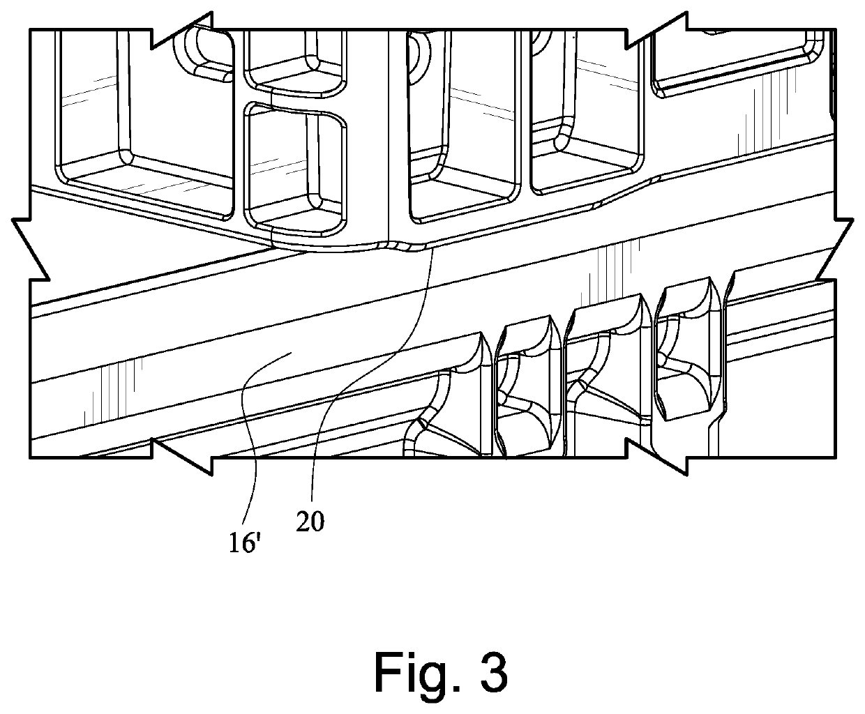
[0008]A guide rib for blind-stacking provides a positive locking of the base to the top of the sidewall of the crate below. This could be accomplished by a protrusion (rib) extending over the stacking rim, creating a positive lock with the side wall while sliding the crate into the nested position. The rib may be as close as possible to the front of the base to maximize engagement. It can be either at the perimeter of the stacking rim (simple for mold built) or in the middle to engage in a groove (which requires additional slide action in the mold).

Problems solved by technology

It is difficult to manually blind-stack crates with heavy loads.
It is a common problem that the top of crate walls could be pushed outwards when stacked.
When this happens, the bottom of the top crate loses contact to the wall below, which triggers a significant loss of stacking strength of the crate column and a high risk that the stack could collapse.
This scenario creates a high risk of injuries and damaged product.
That is, with existing crates, the side walls of the lower crate in a stack of crates tend to bend outwards under the load of the top crate, and the top crate could drop into the lower crate and damage the contents or packaging.
With existing designs, it is also time-consuming to correct any misalignment.

Method used


Image

  • Blind-stack and nest-interlock container
  • Blind-stack and nest-interlock container
  • Blind-stack and nest-interlock container

Examples


Embodiment Construction

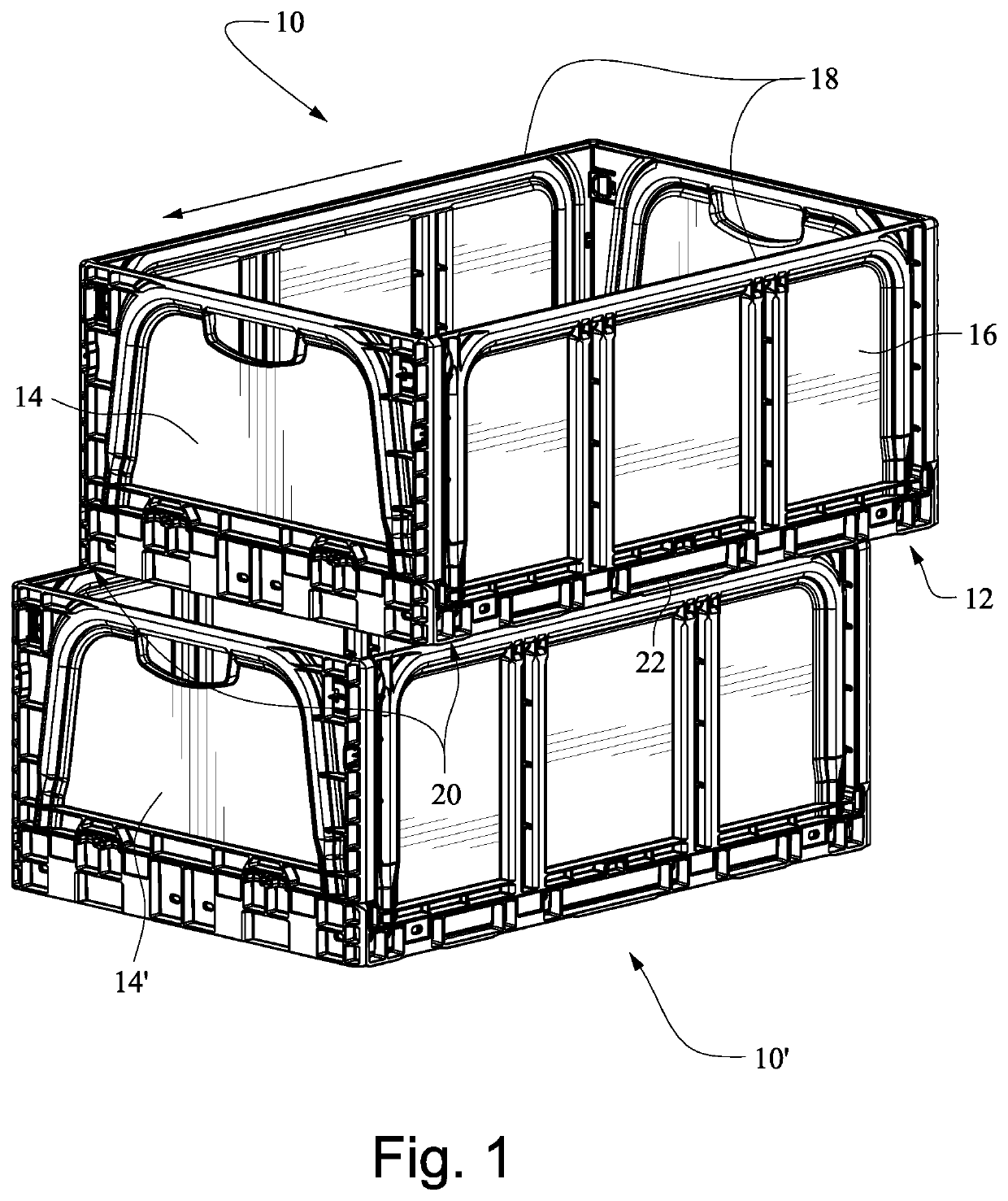
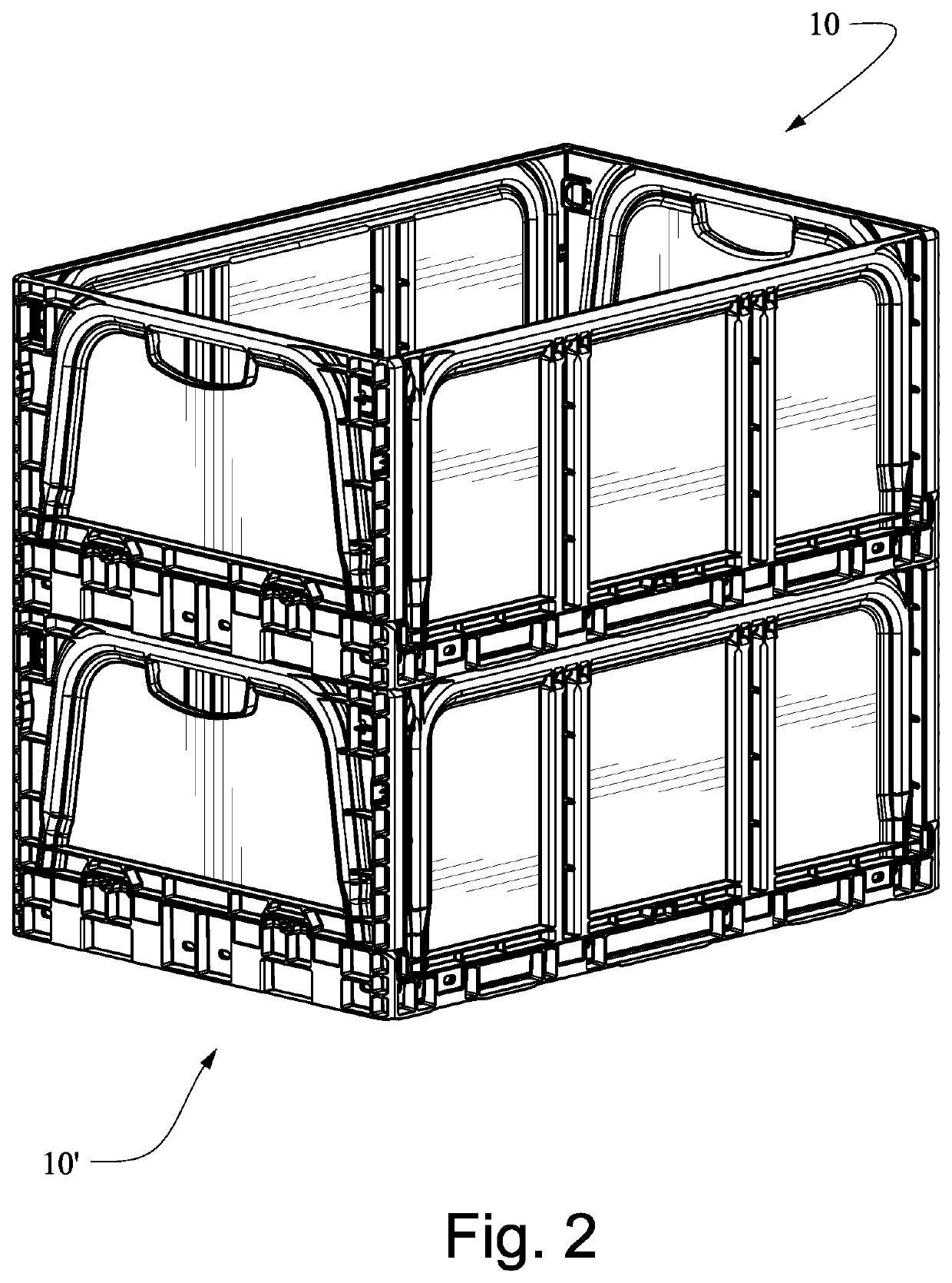
[0020]FIGS. 1 and 2 show a crate 10 according to described embodiments configured for blind-stacking on an adjacent crate 10′. The crate 10 includes a bottom panel 12, end walls 14 protruding from the bottom panel 12, and sidewalls 16 extending from the bottom panel and connected between the end walls 14. The sidewalls 16 include a stacking rim 18 on a top surface.

[0021]In order to facilitate blind-stacking, the bottom panel 12 is provided with one or more guide ribs 20 generally under or aligned with the sidewalls 16.

[0022]With reference to FIGS. 3 and 4, in some embodiments, the guide ribs 20 are positioned adjacent forward ends of the crate 10 (relative to the direction of travel), where the guide ribs 20 are sized and shaped to positively engage the sidewalls 16′ of the adjacent crate 10′. The guide rib 20 thus provides a positive locking of the bottom panel 12 to the top of the sidewalls 16′ of the adjacent crate 10′. The positive lock with the sidewalls 16′ can be maintained w...


PUM


Abstract

A crate is configured for blind-stacking on an adjacent crate with side walls. The crate may include a bottom panel, end walls extending from the bottom panel, and side walls extending from the bottom panel and connected between the end walls. The side walls include a stacking rim on a top surface. The bottom panel may include guide ribs under the side walls, respectively, and positioned adjacent a forward end of the crate. The guide ribs may be sized and shaped to positively engage the side walls of the adjacent crate, and the guide ribs may be configured to prevent the side walls of the adjacent crate from deflecting outward under load. The crate facilitates blind-stacking and helps to minimize the effort for an operator to handle heavier loads.

Description

CROSS-REFERENCES TO RELATED APPLICATIONS[0001]This application claims the benefit of U.S. Provisional Patent Application No. 62 / 474,159, filed Mar. 21, 2017, the entire content of which is herein incorporated by reference.STATEMENT REGARDING FEDERALLY SPONSORED RESEARCH OR DEVELOPMENT[0002](Not Applicable)BACKGROUND[0003]The invention relates to crates and, more particularly, crates that are configured to facilitate blind-stacking and to prevent crate walls from deflecting under load.[0004]The term “blind-stacking” refers to sliding a top crate in a stack of crates along the side of an adjacent crate into a nested position. The top crate is self-guided on the walls of the lower crate. The bottom of the top crate is gliding on top of the adjacent wall until the crate finds its nested position. Blind-stacking is used to column stack crates. It is difficult to manually blind-stack crates with heavy loads.[0005]Additionally, the term “nest interlock” refers to preventing the walls of th...

Claims


Application Information

Patent Timeline
Patent Type & Authority Patents(United States)
IPC IPC(8): B65D21/02B65D21/032
CPCB65D21/0213B65D21/0235B65D21/0212B65D21/0202
Inventor SOMMER, AXEL
Owner MONOFLO INT
Learn More