
Combined stimulator and bipolar electrode assembly for mouse electroretinography (ERG)

a bipolar electrode and stimulator technology, applied in the field of apparatus and methods for the assessment of ophthalmic physiological signals, can solve the problems of time-consuming and labor-intensive, conducting ophthalmic electrophysiology on a mouse, and requiring special skills, and achieve the effect of quick and easy performing ophthalmic electrophysiology

Active Publication Date: 2020-11-03
DIAGNOSYS LLC
View PDF38 Cites 2 Cited by
  • Summary
  • Abstract
  • Description
  • Claims
  • Application Information

AI Technical Summary

Benefits of technology

The present invention is a new method and device that makes it quick and simple to conduct electrophysiology on mice to help with ophthalmic research.

Problems solved by technology

Mispositioning of the reference electrode will cause imbalances in the readings between the two eyes of the mouse.
An added complication is that, usually, all this must be done in a room only dimly illuminated by deep red light.
Either movement may disturb the electrodes placed on the mouse, which would then require that the electrodes be repositioned.
It will be appreciated that conducting ophthalmic electrophysiology on a mouse is time-consuming and requires personnel with special skills.
Although some of these deficits can only be detected using ophthalmic electrophysiology, electrophysiology was initially excluded from the testing protocols because existing techniques for performing ophthalmic electrophysiology on mice are too time-consuming and require personnel with rare skills.
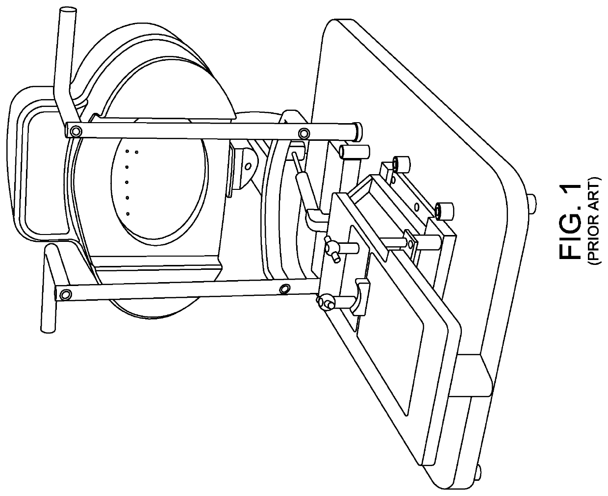
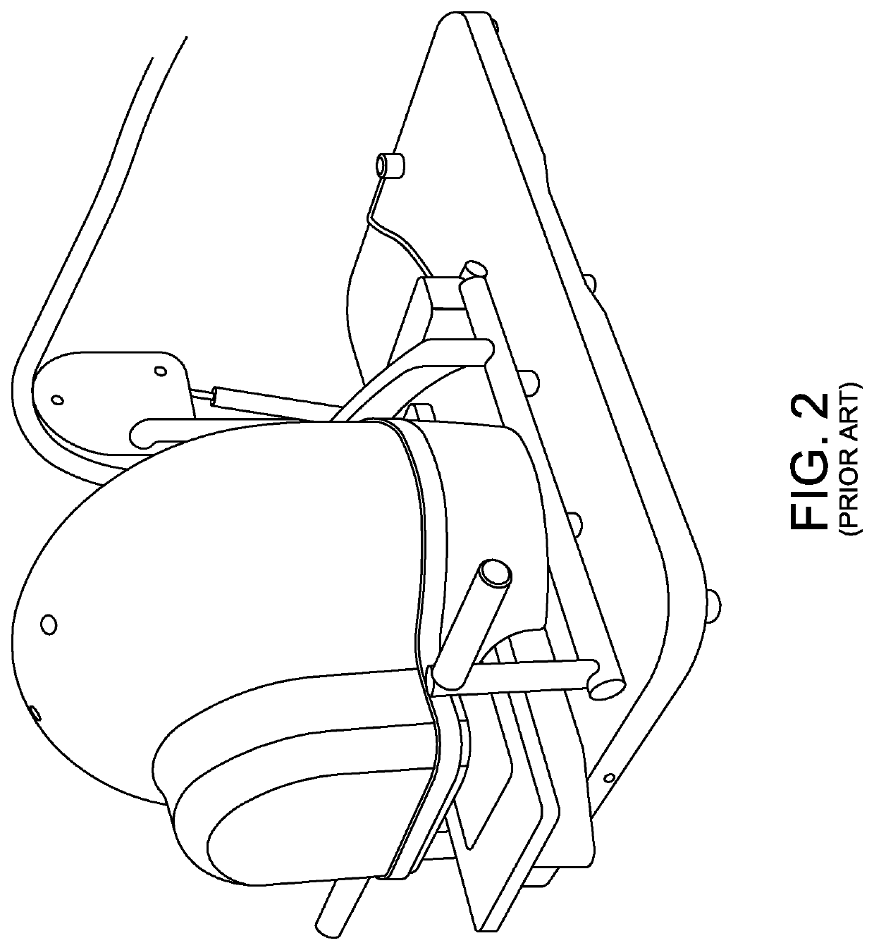
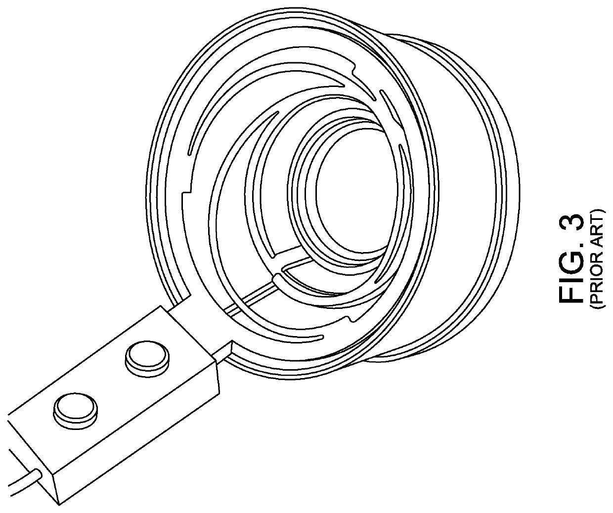
There is an existing device (a “contact lens bipolar corneal electrode”) that does this effectively for humans, but in its present state the contact lens bipolar corneal electrode is not practical for widespread use with mice.
As noted above, human contact lens bipolar corneal electrodes work effectively, but mouse contact lens bipolar corneal electrodes are impractical for widespread use with mice.
More particularly, a mouse contact lens bipolar corneal electrode is available from Hansen Labs, but the mouse contact lens bipolar corneal electrode is impractically delicate, expensive, and hard to make.
The basic problem with the mouse contact lens bipolar corneal electrode sold by Hansen Labs is that the manufacturer does not know how its customers are going to use the lens—they may have an application that needs the animal to view an image—and so the manufacturer has to start by wrapping a corneal electrode around an optically “good”, zero-power mouse contact lens, and this is a challenging task.
Another problem with mouse contact lens bipolar corneal electrodes is that, if anything, they slow the testing process down rather than speed it up.
The mouse contact lens bipolar corneal electrodes are so delicate and sensitive that they require great care and skill in order to place them properly on the eye of the mouse—by way of example but not limitation, it is very easy to accidentally cover the mouse contact lens bipolar corneal electrodes with saline solution which shorts them out, and they often break during handling.
In any case, mouse contact lens bipolar corneal electrodes are so hard to make that they are usually now offered only in monopolar versions, which means that the problem of placing the reference electrode on the mouse is still left to the user.

Method used


Image

  • Combined stimulator and bipolar electrode assembly for mouse electroretinography (ERG)
  • Combined stimulator and bipolar electrode assembly for mouse electroretinography (ERG)
  • Combined stimulator and bipolar electrode assembly for mouse electroretinography (ERG)

Examples


Embodiment Construction

[0042]The present invention provides a new and improved approach for quickly and easily performing ophthalmic electrophysiology on mice.

[0043]More particularly, and looking now at FIGS. 6-11, there is shown a combined stimulator and bipolar electrode assembly 5 formed in accordance with the present invention. Combined stimulator and bipolar electrode assembly 5 generally comprises a housing 10, a light pipe subassembly 15 and a light source subassembly 20.

[0044]Housing 10 preferably comprises a main body 22 having a cavity 25 formed therein, and a side arm 30 extending at an angle (e.g., 125 degrees) to the longitudinal axis of main body 22. Side arm 30 includes a cavity 35 formed therein, and a magnetic mount 40 (preferably in the form of a steel ball) secured to side arm 30.

[0045]Light pipe subassembly 15 is disposed partially within, and protrudes from, cavity 25 of main body 22. Light pipe subassembly 15 generally comprises a light pipe 45 formed out of a light-transmissive mate...


PUM


Abstract

Apparatus for evoking and sensing ophthalmic physiological signals in an eye, the apparatus comprising: an elongated tubular light pipe having a longitudinal axis, a distal end and a proximal end, the distal end terminating in a spheroid recess; an active electrode having a distal end and a proximal end, the active electrode being mounted to the elongated tubular light pipe and extending proximally along the elongated tubular light pipe so that the distal end of the active electrode terminates at the spheroid recess at the distal end of the elongated tubular light pipe; and a reference electrode having a distal end and a proximal end, the reference electrode being mounted to the elongated tubular light pipe and extending proximally along the elongated tubular light pipe so that the distal end of the reference electrode terminates at the spheroid recess at the distal end of the elongated tubular light pipe; wherein the distal end of the active electrode is located closer to the longitudinal axis of the elongated tubular light pipe than the distal end of the reference electrode.

Description

REFERENCE TO PENDING PRIOR PATENT APPLICATION[0001]This patent application claims benefit of prior U.S. Provisional Patent Application Ser. No. 62 / 160,503, filed May 12, 2015 by Diagnosys LLC and Bruce Doran et al. for COMBINED STIMULATOR AND BIPOLAR ELECTRODE ASSEMBLY FOR MOUSE ELECTRORETINOGRAPHY (ERG), which patent application is hereby incorporated herein by reference.FIELD OF THE INVENTION[0002]This invention relates generally to apparatus and methods for the assessment of electrophysiological signals, and more particularly to apparatus and methods for the assessment of ophthalmic physiological signals.BACKGROUND OF THE INVENTION[0003]Full-field ophthalmic electrophysiology generally involves flashing a light from a large “bowl” into the eye of the subject, and then measuring the response from the retina of the subject using electrodes, i.e., an active electrode which contacts the eye of the subject and other electrodes (reference and ground electrodes) which contact other port...

Claims


Application Information

Patent Timeline
Patent Type & Authority Patents(United States)
IPC IPC(8): A61B5/0496A61B3/00A61B5/00A61B90/30
CPCA61B5/6821A61B3/0008A61B5/0496A61B2562/0209A61B2562/182A61B2503/42A61B2503/40A61B2090/306A61B5/398
Inventor DORAN, BRUCECHABOT, MARC
Owner DIAGNOSYS LLC
Learn More