


Quick Research
Generate reliable direction feasibility study reports for your R&D in just a few steps.

Technical Q&A
Discover and master advanced knowledge NOW. Basics, ideas, possibilities, all at once.

Find Solutions
As an expert in R&D theories, this can generate solutions to your technical problems instantly.

Evaluate Feasibility
Analyze your overall solution with one click, know your potential R&D risks in advance.

Monitor Landscape
Get weekly tech updates, stay abreast of the latest tech innovations and key insights.
Non-invasive radio-frequency ablation system
a radiofrequency ablation and non-invasive technology, applied in the field of non-invasive radiofrequency ablation systems, can solve the problems of limited treatment depth, invasive rfa treatment techniques, and peripheral non-targeted tissue thermal damage or necrosis, so as to reduce the risk of treatment complications and eliminate bleeding or perforation
- Summary
- Abstract
- Description
- Claims
- Application Information
AI Technical Summary
Benefits of technology
Problems solved by technology
Method used
Image

Examples
embodiment 1
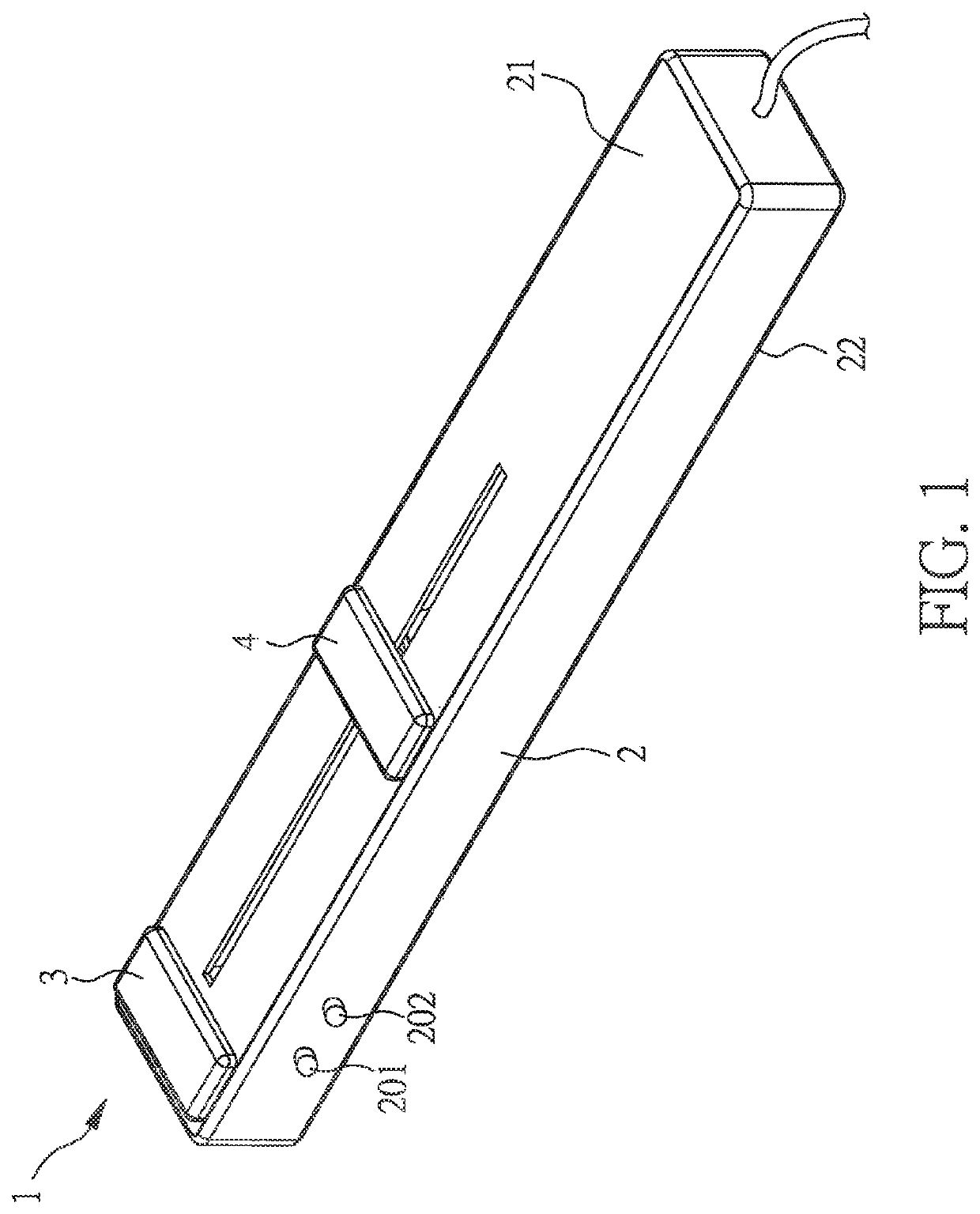
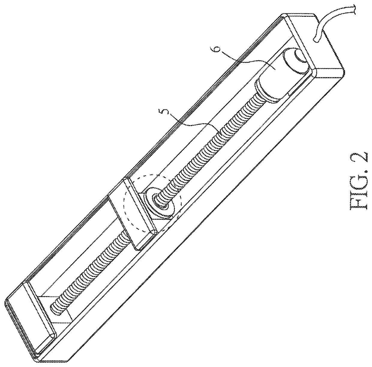
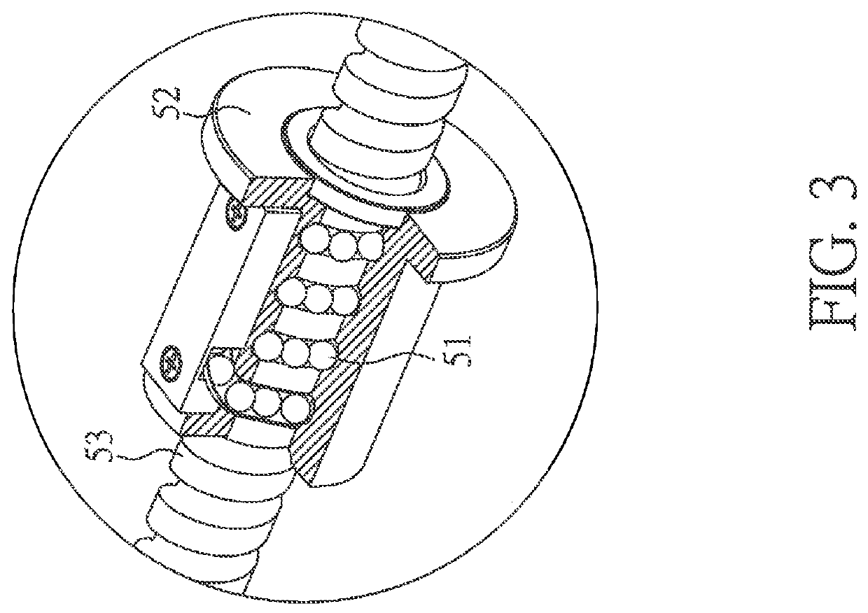
[0034]FIG. 1 is a schematic diagram of an ablation device of a first preferred embodiment, FIG. 2 is a partial schematic diagram of the embodiment of FIG. 1; FIG. 3 is a schematic diagram showing a partial enlargement of the moving unit of FIG. 2. This embodiment includes: an ablation device 1 comprising: a substrate 2 having a first surface 21; a first electrode 3 disposed on the first surface 21; a second electrode 4 disposed on the first surface 21 and adjacent to the first electrode 3; a moving unit 5 electrically connected to the second electrode 4 for moving the second electrode 4 to regulate the distance between the second electrode 4 and the first electrode 3; and a radio frequency generator (not shown) connected to the ablation device 1 for providing a radio frequency current to the first electrode 3 and the second electrode 4. The moving unit 5 is a ball screw, as shown in the partial enlargement diagram of FIG. 3. The ball screw 5 improves poor positioning and prevents da...
embodiment 2
[0036]FIG. 4 is a schematic diagram of an ablation device of another embodiment of the present invention. The ablation device of the non-invasive radio-frequency ablation system in the present embodiment is similar to that of Embodiment 1 except for the following differences.
[0037]Referring to FIG. 4, the ablation device in the present embodiment may optionally comprise a cooling unit 7, a temperature sensing unit 8, and a treatment depth sensing unit 9. The cooling unit 7 may be disposed on the first surface 21 of the substrate 2 and between the first electrode 3 and the second electrode 4. In the present embodiment, the ablation device is illustrated as including each of the cooling unit 7, the temperature sensing unit 8 and treatment the depth sensing unit 9. However, any one or more of the cooling unit 7, the temperature sensing unit 8 and treatment depth sensing unit 9 may also be omitted.
[0038]The cooling unit 7 may include a cooling chip and / or a refrigerant to lower the temp...
embodiment 3
[0041]FIG. 5 is a schematic diagram of an ablation device according to another embodiment of the present invention. The ablation device of the non-invasive radio-frequency ablation system in the present embodiment is similar to that of Embodiment 1 or 2 except for the following differences.
[0042]Referring to FIG. 5, the ablation device of the present embodiment may optionally comprise a cooling unit 7, a temperature sensing unit 8, and a treatment depth sensing unit 9. The cooling unit 7 may be disposed on the first surface 21 of the substrate 2 and between the first electrode 3 and the second electrode 4.
[0043]The temperature sensing unit 8 may be disposed on the second surface 22 of the substrate 2 and opposite to the first electrode 3, but the location of the temperature sensing unit may be varied without departing from the invention.
[0044]The treatment depth sensing unit 9 may be disposed on the second surface 22 of the substrate 2 and opposite to the cooling unit 7, but the loc...
PUM
| Property | Measurement | Unit |
|---|---|---|
| current | aaaaa | aaaaa |
| time | aaaaa | aaaaa |
| ablation depth | aaaaa | aaaaa |
Abstract
Description
Claims
Application Information
 - R&D Engineer
- R&D Manager
- IP Professional
- Industry Leading Data Capabilities
- Powerful AI technology
- Patent DNA Extraction
Browse by: Latest US Patents, China's latest patents, Technical Efficacy Thesaurus, Application Domain, Technology Topic, Popular Technical Reports.
© 2024 PatSnap. All rights reserved.Legal|Privacy policy|Modern Slavery Act Transparency Statement|Sitemap|About US| Contact US: help@patsnap.com