Optical module for terabit switch

a technology of optical modules and switches, applied in the direction of lasers, transmission, semiconductor laser arrangements, etc., can solve the problems of limiting the use of conventional switches, the density of interconnects and power consumption of switch modules can be a bottleneck to the system, and the limitations of the architecture even mor

Active Publication Date: 2020-09-22
BROADEX TECH UK LTD
View PDF11 Cites 0 Cited by
  • Summary
  • Abstract
  • Description
  • Claims
  • Application Information

AI Technical Summary

Benefits of technology

The invention describes a switch module that integrates a switch integrated circuit (IC) with multiple photonic integrated circuits (PICs) and planar lightwave circuits (PLCs). The PICs generate light using multiple light sources, while the optical splitter splits the light into multiple parts which are then modulated by the PLCs. The PLCs combine the modulated optical signals to form a single output optical signal. This design allows for high-speed switching and improved optical signal control.

Problems solved by technology

Given the large number of lanes, the interconnect density and power consumption of the module can be a bottleneck to the system.
As the switch ICs improve in performance, the switch modules are even more limited by the constraints of the architecture.
Accordingly, the conventional switch is seriously limited by the architecture of a central switch IC connected to optical transceivers in the front panel, and the constraints are increasing with newer generations of switches.
These constraints may include:Cost of the optical transceivers.Power consumption, where perhaps 30%-50% of the total power is expended in equalizing / regenerating electrical signals as data is transferred back and forth from the switch IC and in / out of the transceivers.
A considerable amount of power may be consumed by the optical transceivers on the front panel, where airflow is often restricted.Panel density—the size of the transceivers is such that a limited number of them can be placed on the front panel and thus only a limited bandwidth out of the front panel of the switch.

Method used


Image

  • Optical module for terabit switch
  • Optical module for terabit switch
  • Optical module for terabit switch

Examples


Embodiment Construction

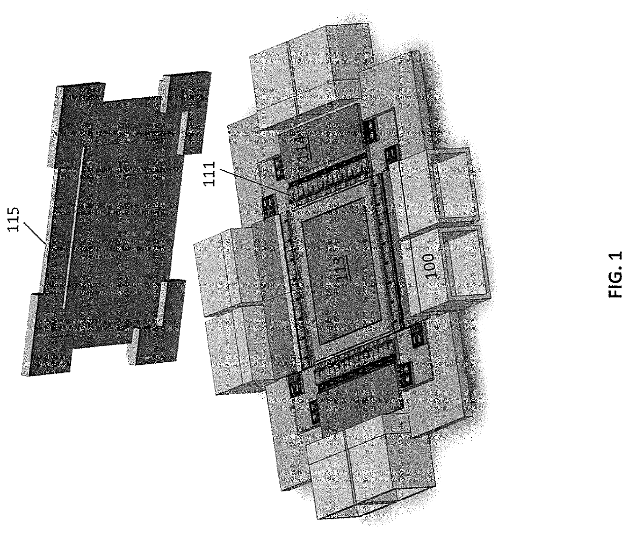
[0029]FIG. 1 shows a switch module in accordance with aspects of the invention. The switch module may perform, for example, routing of data between servers in a data center. The switch module includes a switch integrated circuit (IC) 113. The switch IC routes data between inputs and outputs of the switch IC. The switch IC, and specifically the inputs and outputs of the switch IC, are coupled to a plurality of optical modules. The optical modules comprise an optical assembly 111, a PLC 114, and, only in some embodiments and as illustrated in FIG. 1, a connector for coupling optical fiber lines. The optical assemblies in some embodiments comprise a PIC and a MEMS. The optical assemblies convert outgoing data from the switch IC from electrical signals to optical signals, and convert incoming data to the switch from optical signals to electrical signals. Each optical assembly is coupled to a corresponding PLC 114, with the PLCs in turn coupled to corresponding MTP connectors 100. Each P...


PUM

PropertyMeasurementUnit
wavelengthaaaaaaaaaa
wavelength spacingaaaaaaaaaa

Abstract

A switch module includes a switch integrated circuit (IC), a photonic integrated circuit (PIC), and a planar lightwave circuit (PLC). The PIC may include a plurality of light sources, an optical splitter, and a plurality of modulators. A dual MEMS may be used to align lens arrays, which may be used to couple light from the PIC to the PLC.

Description

CROSS-REFERENCE TO RELATED APPLICATIONS[0001]This application is a continuation of U.S. patent application Ser. No. 15 / 706,457, filed Sep. 15, 2017, which claims the benefit of the filing date of U.S. Provisional Patent Application No. 62 / 395,802, filed on Sep. 16, 2016, the disclosures of which are incorporated by reference herein.BACKGROUND OF THE INVENTION[0002]The present application relates generally to fiber optic communications and more particularly to switching devices having fiber optic connections.[0003]Much of our cloud based infrastructure is based on storage and processing of data by large numbers of servers in data centers. These servers are connected through a switch network in various configurations. A typical topology might be large groups of 96 servers in a rack connected to a top of rack (TOR) switch. These TOR switches are connected to an aggregation or leaf switch, which in turn is connected to a spine switch. The spine switches are interconnected to form a huge...

Claims


Application Information

Patent Timeline
Patent Type & Authority Patents(United States)
IPC IPC(8): G02B6/12H01S5/022H01S5/40H01S5/026G02B6/35H04B10/50G02B6/42H04B10/80H01S5/00H01S5/50G02B6/38G02B6/36
CPCG02B6/4215H04B10/506G02B6/12004G02B6/3596H01S5/0085H01S5/0265G02B6/4292H01S5/4087G02B6/12019H01S5/02248H04B10/801G02B6/3598H01S5/4025H01S5/0268H01S5/50G02B6/3672H01S5/4012G02B6/3885H01S5/02325
Inventor PEZESHKI, BARDIATON, DINHHECK, SUSANNAHYOFFE, GIDEONSOLDANO, LUCASBULTHUIS, HENKRANGARAJAN, SURESHSTOKES, JAMIESELIM, RAMSEY
Owner BROADEX TECH UK LTD
Why Eureka
Try Eureka