
Fitting and method of manufacturing a fitting for attaching flexible tube to rigid tube

a technology of rigid tube and fitting, which is applied in the direction of hose connection, pipe connection arrangement, mechanical apparatus, etc., can solve the problems of fitting and joint taking corners, and achieve the effect of sufficient rigidity and strength, simple and inexpensive form

Active Publication Date: 2020-09-08
ANDERSON COPPER & BRASS COMPANY
View PDF13 Cites 0 Cited by
  • Summary
  • Abstract
  • Description
  • Claims
  • Application Information

AI Technical Summary

Benefits of technology

[0009]The present invention is directed to a fitting configured specifically for joining rigid polymeric tube to flexible tube. The fitting is simple and inexpensive to form and nonetheless provides sufficient rigidity and strength for attaching a flexible tube to the fitting via a compression ring or band clamp.

Problems solved by technology

A disadvantage of rigid polymeric tube is that it does require fitting and joints to take corners.

Method used


Image

  • Fitting and method of manufacturing a fitting for attaching flexible tube to rigid tube
  • Fitting and method of manufacturing a fitting for attaching flexible tube to rigid tube
  • Fitting and method of manufacturing a fitting for attaching flexible tube to rigid tube

Examples


Embodiment Construction

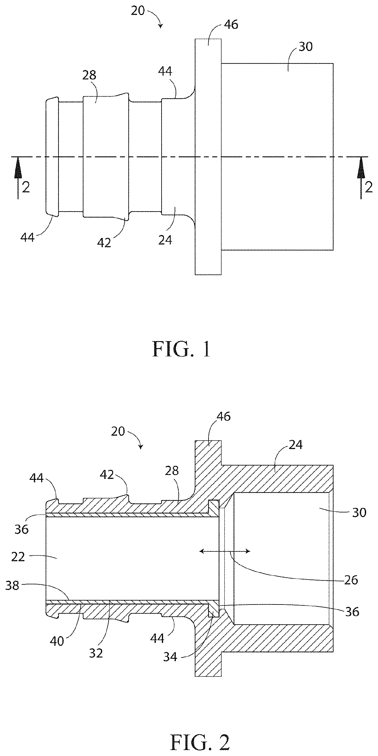
[0020]A joint fitting (20) in accordance with the invention for joining rigid tube to flexible tube is shown in the drawing figures. The joint fitting (20) comprises a metal body (22) and polymeric body (24). The joint fitting (20) comprises a fluid passageway (26) that extends through the fitting and that is configured to create a fluid connection between the rigid tube and flexible tube attached to the fitting. One end of the joint fitting (20) comprises a barbed or ridged male fitting (28) that is configured to be inserted into an end of flexible tube. The other end of the joint fitting (20) comprises a female socket (30) that is configured to receive an end of rigid tube. The joint fitting (20) as shown is linear. In other words, the female socket (30) and the male fitting (28) are axially aligned. However, it should be appreciated that a joint fitting (20) in accordance with the invention need not be linear and could be, for example, an elbow joint fitting.

[0021]The metal body ...


PUM

PropertyMeasurementUnit
flexibleaaaaaaaaaa
axis of symmetryaaaaaaaaaa
inner diameteraaaaaaaaaa

Abstract

A fitting for attaching flexible tube to rigid tube comprises a fluid passageway, a tubular metal body, and a polymeric body. The fluid passageway extends through the tubular metal body and the polymeric body is interlocked with the metal body. The polymeric body encircles the fluid passageway and the metal body. A portion of the polymeric body that encircles the metal body forms a male fitting that comprises at least one annular rib or barb and that is configured and adapted to snugly slip into the end of a flexible tube with a press fit. A portion of the polymeric body extends beyond the metal body along the fluid passageway and defines a female socket that is configured and adapted to snugly receive an end of a rigid tube. The socket is configured and adapted to be solvent bondable to polymeric material.

Description

CROSS-REFERENCE TO RELATED APPLICATIONS[0001]Not Applicable.STATEMENT REGARDING FEDERALLY SPONSORED RESEARCH OR DEVELOPMENT[0002]Not Applicable.APPENDIX[0003]Not Applicable.BACKGROUND OF THE INVENTIONField of the Invention[0004]The present invention pertains to fittings for attaching relatively flexible tube / plumbing, such PEX tube, to relatively rigid tube / plumbing, such as CPVC or PVC tube. More particularly, the present invention pertains to fitting comprising a tubular metal body encircled by an overmolded polymeric body, wherein the metal body provides rigidity for crimping flexible tube around the polymeric material that encircles the metal body and the polymeric body forms a fitting for solvent bonding a rigid polymeric tube to the fitting.General Background[0005]As used in the present application, rigid tube / plumbing means tube / plumbing that is typically installed without intentionally deforming the tube / plumbing around turns during installation. Fittings are typically used ...

Claims


Application Information

Patent Timeline
Patent Type & Authority Patents(United States)
IPC IPC(8): F16L33/30F16L33/207F16L47/02
CPCF16L47/02F16L33/30F16L33/2071
Inventor WARREN, DAVID R.BONADONA, DAVID J.ABUELIZAM, SALEM
Owner ANDERSON COPPER & BRASS COMPANY
Learn More