Head protection device and respirator device

a technology for protecting devices and head, applied in the field of head protection devices, can solve problems such as collisions in the state of the ar

Active Publication Date: 2020-09-08
DRAGER SAFETY
View PDF11 Cites 0 Cited by
  • Summary
  • Abstract
  • Description
  • Claims
  • Application Information

AI Technical Summary

Benefits of technology

[0010]A basic object of the present invention is therefore to provide the most compact head protection device possible of the above-mentioned type. In particular, the air duct belonging to the head protection device and the visor shall be arranged in a space-saving manner in relation to one another.
[0012]A basic idea of the present invention is to provide the swivel joints with a dual function. Consequently, the swivel joints fasten the visor rotatably at the head bracket. In addition, the swivel joints each form a part of the air duct. One of the air outlets of the air duct, namely, the forehead outlet, is not usually in conflict with the visor in respect to the space needed for construction. By contrast, it may lead to a collision in the state of the art with the at least one joint of the head protection device and / or with the visor in the part of the air duct that extends to the at least one chin air outlet, especially when the visor is designed as a visor foldable to the head bracket by means of the joints. Due to the at least one swivel joint forming an air channel extending from the head bracket to the visor as a part of the air duct, the air duct as a whole can be integrated in the head protection bracket in a more compact manner. The air duct can thus extend at first close to the head bracket from an area corresponding to the back of the head to an area corresponding to the forehead area, where the air duct will then branch out in order to lead to the forehead air outlet with one branch and to the air channel formed by the at least one joint with another branch. The air duct can then lead farther with the corresponding branch to the chin area. The visor can be folded with such a design relative to the head bracket without there being any collision in the area closely surrounding the joints between the visor and the air duct, because the air duct is formed in said area at least partially by the joints, or by at least one of the joints, themselves. This collision-free design makes it possible to create an especially compact air duct as well as head bracket for the head protection device, the visor being fastened to the head bracket, mounted by swivel joints.
[0014]One advantageous embodiment of the head protection device is characterized in that each swivel joint has a hollow cylindrical joint housing and a hollow shaft held by the joint housing in a rotating manner, wherein the corresponding air channel passes through the hollow shaft. The hollow shaft of the particular joint is consequently used in this case to form the respective corresponding air channel. The visor can therefore be rotated or folded in relation to the head bracket without interrupting the air duct, especially to the at least one chin outlet. The branched air duct is therefore protected from external contaminating effects, for example, dust or sand, even when the visor is rotated and / or the visor is folded up. Therefore, only the air introduced through the air inlet will flow from the air outlets of the air duct.
[0016]Another advantageous embodiment of the head protection device is characterized in that each air channel is configured to guide air to a chin outlet. The air channels are defined in this case as the air channels formed by the swivel joints. Air flowing into the air duct through the air inlet is sent proportionately to the head bracket-side inlet of the air channel formed by the respective swivel joint, so that a corresponding percentage of the air flows through the air channel. Provisions are preferably made based on this for an air duct element to adjoin the joint on the outside, with the air duct element forming another air channel, which leads the air channel formed by the respective joint farther to the chin air outlet. It proved to be advantageous for an especially compact design of the head protection device if the air duct element is formed by a frame, especially by a frame section, of the visor. The frame or frame section of the visor has a dual function in this case, which keeps the space necessary for construction for the head protection device especially small.
[0018]Another advantageous embodiment of the head protection device is characterized in that the visor is configured as a lever for adjusting the rotary throttle valves. The visor is fastened rotatably to the head bracket by means of the two swivel joints. The visor is thus fastened, for example, to the respective hollow shafts of the swivel joints. The hollow shafts will therefore also rotate relative to the joint housings with the folding up of the visor, so that adjustment of the valve means is possible. A reverse embodiment is likewise conceivable, in which the visor is connected, for example, to the joint housings. The user of the head protection device can therefore determine the throttling of the air flow through the respective air channel, which can be affected by means of the rotary throttle valve, with the folding up and especially with the respective opening angle of the visor.
[0023]Another advantageous embodiment of the head protection device is characterized in that the air duct is configured such that when the rotary throttle valves are closed or in the throttling position, between 60% and 80% of the air fed through the air inlet is guided to the chin outlets. In addition, provisions may be made for 60% to 90% of the air flowing through the air inlet to be guided to the forehead outlet when the rotary throttle valves are opened or in a released position. A large percentage of the air flowing through the chin outlets with the visor closed will therefore flow through the forehead outlet when the visor is opened. This reduces the velocity of flow of the air being discharged at the chin outlets when the visor is opened, so that the risk of removal of dust or rock particles from the front side of a helmet or from the front side of the head of the person using the head protection device is thus already markedly reduced. The statements made above therefore apply analogously.

Problems solved by technology

By contrast, it may lead to a collision in the state of the art with the at least one joint of the head protection device and / or with the visor in the part of the air duct that extends to the at least one chin air outlet, especially when the visor is designed as a visor foldable to the head bracket by means of the joints.

Method used


Image

  • Head protection device and respirator device
  • Head protection device and respirator device
  • Head protection device and respirator device

Examples


Embodiment Construction

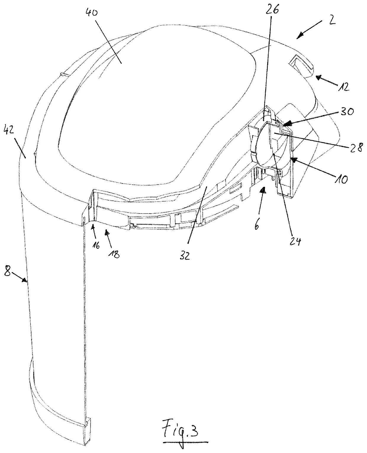
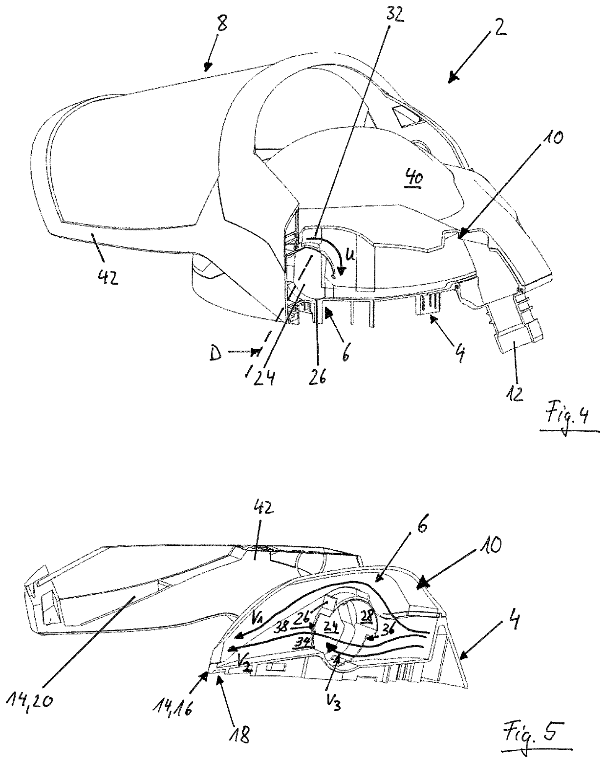
[0032]Referring to the drawings, FIG. 1 shows the head protection device 2 according to the present invention. The head protection device 2 is used to protect the head of a person who is using the head protection device 2. The head protection device 2 has, for this, a head bracket 4. As can be seen in FIG. 1, the head bracket 4 is formed by a helmet 40. The helmet 40 has, at its inner wall, a head strap, with which the helmet 40 can be firmly fastened on the upper body of the person. The term head bracket 4 is consequently defined broadly.

[0033]To protect the face of the person using the head protection device 2, a visor 8 is provided for the head protection device 2. The visor 8 is fastened rotatably at the head bracket 4 or at the helmet 40. Two swivel joints 6, which establish the mechanical connection between the visor 8 and the head bracket 4 or the helmet 40, are provided for this. The visor 8 can be pivoted by means of the swivel joints 6 between a closed position, as it can ...


PUM


Abstract

A head protection device (2), for protecting the head, includes a head bracket (4), with a visor (8) fastened rotatably to the head bracket (4) via two swivel joints (6), and with a branched air duct (10), which has one air inlet (12) and a plurality of air outlets (14). At least one of the air outlets (14) is arranged as a chin air outlet (20) at a lateral section (22) of the visor. At least one of the swivel joints (6) forms an inner air channel (24) extending as a part of the air duct (10) from the head bracket (4) to the visor (8). In addition, a respirator device is provided with the head protection device (2).

Description

CROSS REFERENCE TO RELATED APPLICATIONS[0001]This application claims the benefit of priority under 35 U.S.C. § 119 of German Patent Application 10 2014 019 204.0 filed Dec. 19, 2014, the entire contents of which are incorporated herein by reference.FIELD OF THE INVENTION[0002]The present invention pertains to a head protection device for protecting the head, with a head bracket, with a visor fastened to the head bracket by means of two swivel joints, and with a branched air duct, which has one air inlet and a plurality of air outlets, wherein at least one of the air outlets is arranged as a forehead air outlet at an upper section of the visor, and wherein at least one of the air outlets is arranged as a chin air outlet at a lateral section of the visor.[0003]The present invention pertains, in addition, to a respirator device with an air supply unit for providing an air flow, with a head protection device, which has a branched air duct with at least one air inlet and a plurality of a...

Claims


Application Information

Patent Timeline
Patent Type & Authority Patents(United States)
IPC IPC(8): A62B18/04A62B18/10A62B18/08A42B3/28A62B18/00A42B3/22
CPCA62B18/003A42B3/225A42B3/286A62B18/10A62B18/04A62B18/082A62B7/00A62B18/00A42B3/222A62B18/045A62B18/08A62B18/084
Inventor BALKE, OLAFRADEMACHER, MARTINFRANKE, KATJA
Owner DRAGER SAFETY
Why Eureka
Try Eureka