Flow straightener

a flow rectifier and straightener technology, which is applied in the direction of machines/engines, mechanical equipment, liquid fuel engines, etc., can solve the problems of large flow rectifiers whose parts have diameters of 350 mm, especially of more than 500 mm, and high tool costs of injection molding tools, so as to increase the peak efficiency of axial fans and reduce the efficiency of flow rectifiers. , the effect of easy installation

Active Publication Date: 2020-09-01
EBM PAPST MULFINGEN GMBH & CO KG
View PDF23 Cites 0 Cited by
  • Summary
  • Abstract
  • Description
  • Claims
  • Application Information

AI Technical Summary

Benefits of technology

The invention is a flow rectifier for an axial fan that has a hub and at least one vane, which can be connected and disconnected. This design allows for easy customization of the fan's performance by adding or removing vanes, as needed. The vane geometry can also be easily changed. The flow rectifier is modular, meaning that the hub can be used for different fan sizes by attaching different guide vanes to it, which increases the production run for the hub and reduces part costs. The flow rectifier is also composed of several parts, reducing the size of each part and facilitating the injection-molding process, resulting in lower tool costs and easier handling.

Problems solved by technology

Such large flow rectifiers, whose parts have diameters of 350 mm, especially of more than 500 mm, are expensive: for cost reasons, these parts are usually made of plastic, for example, by means of injection molding.
This calls for injection molding tools that entail high tool costs, especially in the case of large parts.
Moreover, production by means of plastic injection molding is quite difficult with such large parts, particularly in view of their thin walls.
The parts are basically fragile and problematic when it comes to packaging, storage, transportation and handling.
As a result, the required production run for a specific flow rectifier is smaller than that of the corresponding fan and thus especially too small for a cost-effective production run, since a separate injection mold is needed for each variant of the flow rectifier.

Method used


Image

  • Flow straightener
  • Flow straightener
  • Flow straightener

Examples


Embodiment Construction

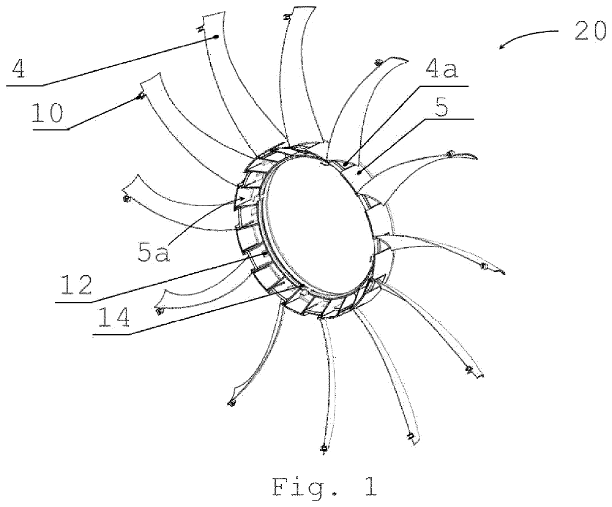
[0028]FIG. 1 shows a flow rectifier 20 according to the invention, in a three-dimensional view. The flow rectifier 20 has a hub 5 and a plurality of vanes 4. The inner circumference of the hub 5 has a circumferential stop 14 as well as latching hooks 12 distributed along the circumference. On their ends facing the center axis 2a of the hub, the vanes 4 have guides 4a by means of which they are inserted along the outer circumference of the hub 5 into guides 5e located there (not visible in this figure). In particular, in this manner, the vanes 4 can be connected to the hub 5 without the need to use tools. Moreover, the vanes 4 each have a connection element 10 in an area on their side facing away from the center axis 2a of the hub.

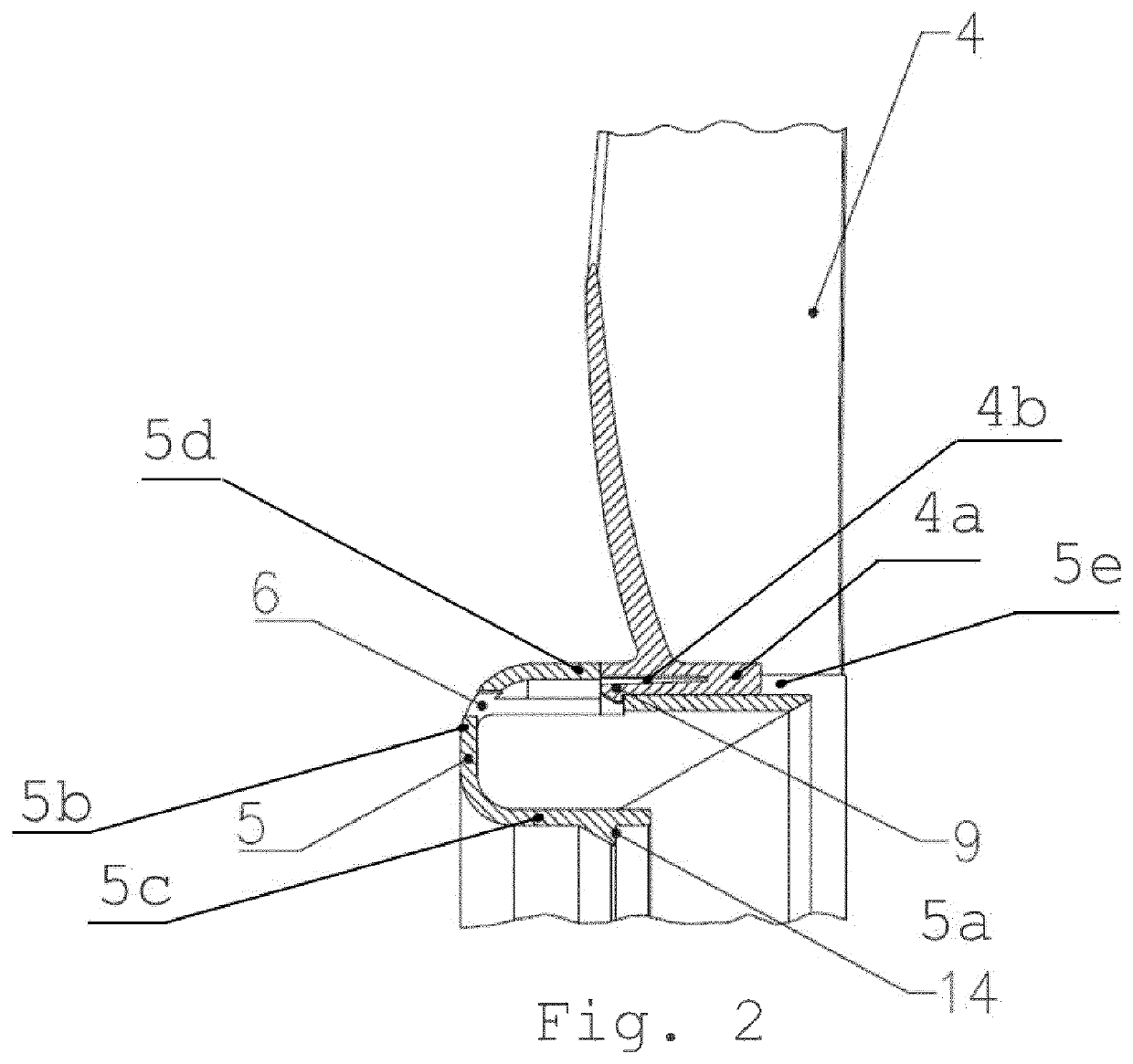
[0029]FIG. 2 shows a section of a flow rectifier according to the invention, in a cross section. A vane 4 is inserted with its guide 4a into the corresponding counterpart of the geometry, namely, the guide 5e of the hub 5. The guides 4a and 5e are configure...


PUM


Abstract

The invention relates to a flow rectifier for an axial fan as well as to an axial fan having a flow rectifier. A flow rectifier according to the invention for an axial fan with a hub and at least one vane is characterized in that the at least one vane can be operatively connected to the hub so as to be detachable. Since the vane and the hub can be connected so as to be detachable, the flow rectifier has a modular structure.

Description

RELATED APPLICATION[0001]This application filed under 35 U.S.C. § 371 is a national phase application of International Application Serial Number PCT / EP2016 / 056278 filed Mar. 22, 2016, which claims priority to European Patent Application No. EP 10 2015 424.1, filed on Mar. 25, 2015, the disclosure of which is entirely incorporated herein by reference.TECHNICAL FIELD[0002]The invention relates to a flow rectifier for an axial fan as well as to an axial fan having a flow rectifier.[0003]In this context, the term “flow rectifier” refers to a baffle element, whereby this baffle element, which is arranged as a flow rectifier downstream from an axial fan, diverts the air that has been made to flow by the axial fan impeller so as to establish a flow that is as axial and uniform as possible. For this purpose, the flow rectifier has at least one appropriately shaped baffle vane.BACKGROUND ART[0004]Fans with large diameters require large flow rectifiers. Such large flow rectifiers, whose parts...

Claims


Application Information

Patent Timeline
Patent Type & Authority Patents(United States)
IPC IPC(8): F04D29/54F04D19/00F04D29/66F04D25/06F04D29/64
CPCF04D29/646F04D25/06F04D29/667F04D19/002F04D29/542F05D2230/51F05D2260/36
Inventor GEBERT, DANIELPISSARCZYK, THORSTENHOSS, SEBASTIAN
Owner EBM PAPST MULFINGEN GMBH & CO KG
Why Eureka
Try Eureka