
Tent

a technology for tents and canopies, applied in tents/canopies, building types, constructions, etc., can solve the problems of reduced usable inner space of tents, inability to achieve, and easy installation, so as to maximize space utilization efficiency, efficient use of space, and cost reduction

Active Publication Date: 2020-09-01
LIVEPLEX
View PDF14 Cites 2 Cited by
  • Summary
  • Abstract
  • Description
  • Claims
  • Application Information

AI Technical Summary

Benefits of technology

The present invention is a tent that has two peaks, which increases the space utilization efficiency compared to conventional tents with a single peak. The tent includes a main pole member and a pair of branch pole members, which allows for the bottom space near the lower end to have the same space as a Teepee tent and overcome the limitation in which the space remarkably decreases towards the upper end of the tent. The tent has a simple configuration and is easily carried out and installed. Y-shaped supporting pole assembly is used to support the sheet of the tent while forming the two peaks, which improves stability when the tent is installed.

Problems solved by technology

However, since the pole stands in the central portion of the tent, an inner space of the Teepee tent remarkably decreases towards an upper portion of the tent, and thus substantial usable inner space of the tent is reduced.
However, such a structure has a limitation in that easy installation and simple structure, which are inherent advantages of the Teepee tent, cannot be achieved.
Also, since additional frames are necessary, the tent increases in weight and volume, and costs of the tent also increase.

Method used


Image

  • Tent
  • Tent
  • Tent

Examples


Embodiment Construction

[0030]Hereinafter, a tent in accordance with the present invention will be described in detail with the accompanying drawings as stated below.

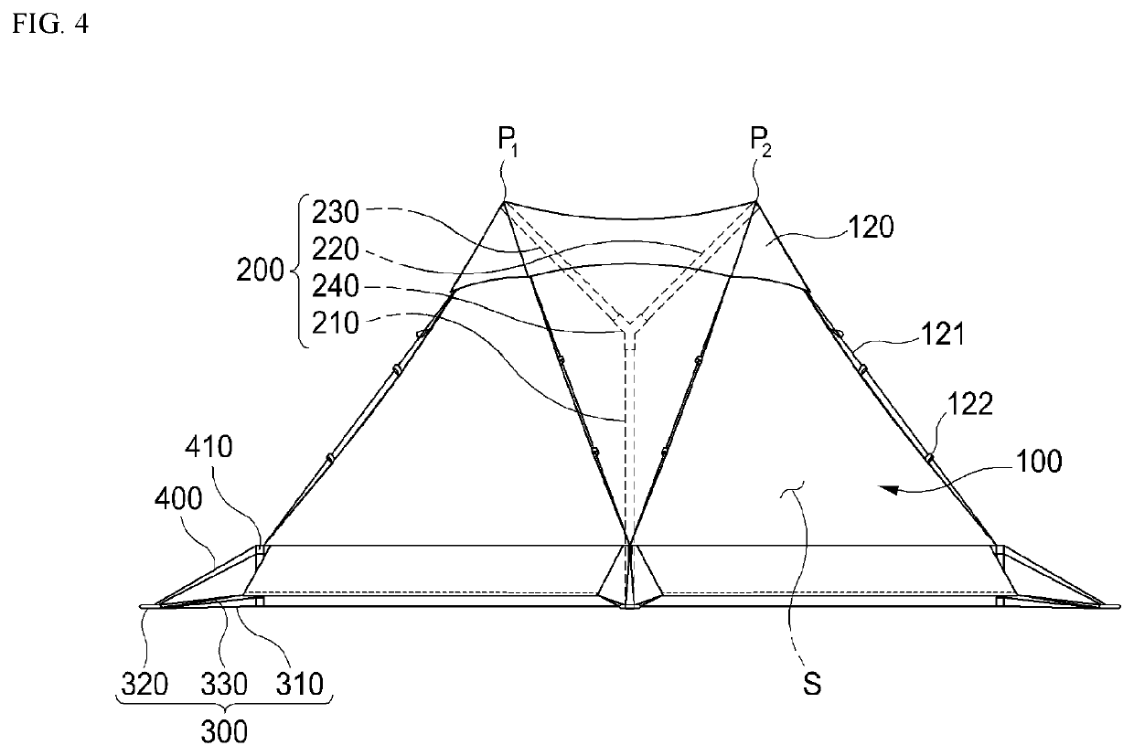
[0031]As illustrated in FIGS. 1 to 7, the tent in accordance with the present invention includes: a sheet 100 that forms an inner space S having two peaks P1, P2; and a supporting pole assembly 200 including a main pole member 210 installed upward in the inner space S and a pair of branch pole members 220, 230 that form the two peaks P1, P2.

[0032]The sheet 100 forms the inner space S having the two peaks P1, P2. Particularly, the sheet 100 is supported by the supporting pole assembly 200 so as to form the inner space S in which a user may live and may have various configuration in accordance with an entire shape and structure of the tent.

[0033]The sheet 100 forms a ceiling and a wall of the tent. In particular, as the sheet 100 is supported by the supporting pole assembly 200, the sheet 100 may form the entire shape of the tent and form ceilin...


PUM


Abstract

A tent including a sheet 100 forming an inner space S having two peaks P1, P2 and a supporting pole assembly 200 including a main pole member 210 installed upward in the inner space S and a pair of branch pole members 220, 230 branched from the main pole member 210 to support the sheet 100, thereby forming the two peaks P1, P2, is disclosed.

Description

TECHNICAL FIELD[0001]The present invention disclosed herein relates to a tent, and more particularly, to a tent capable of enhancing inner space utilization.BACKGROUND ART[0002]A Teepee tent is manufactured based on the model of a Teepee used at a campsite for a tribe having culture of hunting while moving between southern Canada and the plains and northwest North America. The Teepee tent requires only a few components and a relatively simple structure makes installation of the Teepee tent easy.[0003]The Teepee tent may be manufactured from a small sized tent to an extremely large sized tent for accommodating several households and have a shape in which a large stick stands at a central portion of the tent and fabric covers from the ground by using the stick as a supporting pole.[0004]Accordingly, the Teepee tent may excellently keep the inside of the tent warm because the Teepee tent withstands strong wind blown outside, and a fire can be made inside.[0005]However, since the pole s...

Claims


Application Information

Patent Timeline
Patent Type & Authority Patents(United States)
IPC IPC(8): E04H15/26E04H15/60E04H15/16E04H15/24
CPCE04H15/60E04H15/26E04H15/16E04H15/24E04H15/34E04H15/54
Inventor SHIN, DONG IL
Owner LIVEPLEX
Learn More