
Methods to reduce storage capacity

a technology of storage capacity and methods, applied in the field of storage systems, can solve the problems of inefficient use of memory allocated to virtual storage devices, physical storage devices may fail, and be tagged for reallocation, so as to reduce the amount of metadata, quickly replace a failed hard drive, and increase the amount of metadata used for storing data.

Active Publication Date: 2020-08-25
ORACLE INT CORP
View PDF28 Cites 0 Cited by
  • Summary
  • Abstract
  • Description
  • Claims
  • Application Information

AI Technical Summary

Benefits of technology

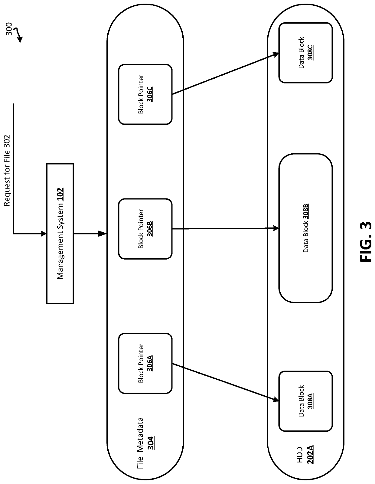
[0004]In one or more embodiments, a virtual storage device may be generated that replicates a layout of a physical storage device it is replacing. The virtual storage device may be used to store data formerly stored in the physical storage device. The layout may detail various configurations of the physical storage device, such as if it implements fixed or variable-block sizes and / or if it implements a level of redundant array of independent disks (RAID). By replicating the layout of a physical storage device that it may replace, the virtual storage device, described within various embodiments, may offer advantages over other virtual storage devices. For example, one alternative approach is to generate and configure a virtual storage device in a manner that is agnostic of one or more physical storage devices in the same storage pool. In such an example, in prior systems, physical storage devices in a storage pool may all implement variable data-block sizes, but a virtual storage device may be generated that implements fixed-data block sizes. Creating such an agnostic virtual storage device may lead to an increase in metadata used for storing data. For example, going from a variable-block size to a fixed-block sizes may require additional block pointers. As a result, creating an agnostic virtual storage device may lead to an inefficient use of memory allocated to the virtual storage device. In contrast, generating a virtual storage device, as described in one or more embodiments of the disclosure, may reduce the amount of metadata typically stored by a virtual storage device, which may allow more data storage within the virtual storage device.
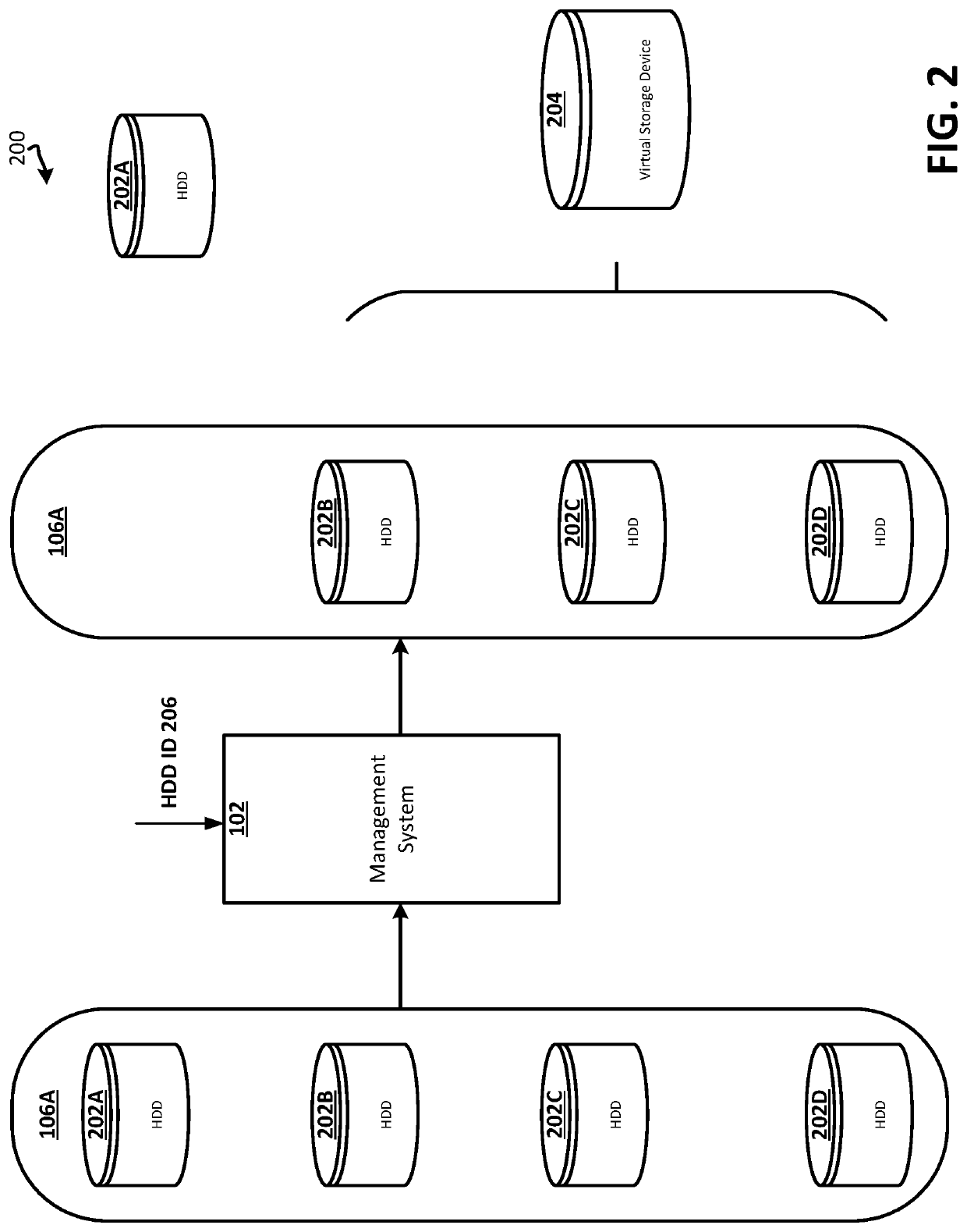
[0005]Generating a virtual storage device, as described in one or more embodiments of the disclosure, may also allow the virtual storage device to be used as a “hot spare.” A virtual storage device may be generated dynamically when needed, which allows the virtual storage device to quickly replace a failed hard drive. In this sense, the virtual storage device is a spare to the failed hard drive. By using a virtual storage device as a hot spare, a storage system may continue to operate without shutting down to replace the failed hard drive. The virtual storage device may be generated and implemented without shutting down the storage system or storage pool that hosts the virtual storage device.
[0006]Furthermore, generating a virtual storage device may allow a hard drive to be reallocated to a different storage pool. A virtual storage device may replicate the layout of a hard drive and appear, to an operating system, that it is the hard drive it is replacing. If the virtual storage device appears as the drive it is replacing, it allows the operating system to reference the virtual storage device by the same means it referenced the hard drive, which does not interrupt the operation of the operating system. Thus, allowing the actual hard disk to be removed seamlessly from the storage pool without an interruption to the operating system. In addition, the hard disk may be reallocated to a different storage pool without interrupting the operating system. The removal and reallocation of the hard drive may reduce the memory capacity of the storage pool and increase the memory of a different storage pool, all while not requiring the storage system to shut down. Several other advantages of the techniques described within this disclosure may be realized by one skilled in the art.

Problems solved by technology

In some instances, a physical storage device may fail, be tagged for reallocation, or be flagged for removal from a storage pool.
As a result, creating an agnostic virtual storage device may lead to an inefficient use of memory allocated to the virtual storage device.

Method used


Image

  • Methods to reduce storage capacity
  • Methods to reduce storage capacity
  • Methods to reduce storage capacity

Examples


Embodiment Construction

[0015]In the following description, for the purposes of explanation, specific details are set forth in order to provide a thorough understanding of certain inventive embodiments. However, it will be apparent that various embodiments may be practiced without these specific details. The figures and description are not intended to be restrictive. The word “exemplary” is used herein to mean “serving as an example, instance, or illustration.” Any embodiment or design described herein as “exemplary” is not necessarily to be construed as preferred or advantageous over other embodiments or designs.

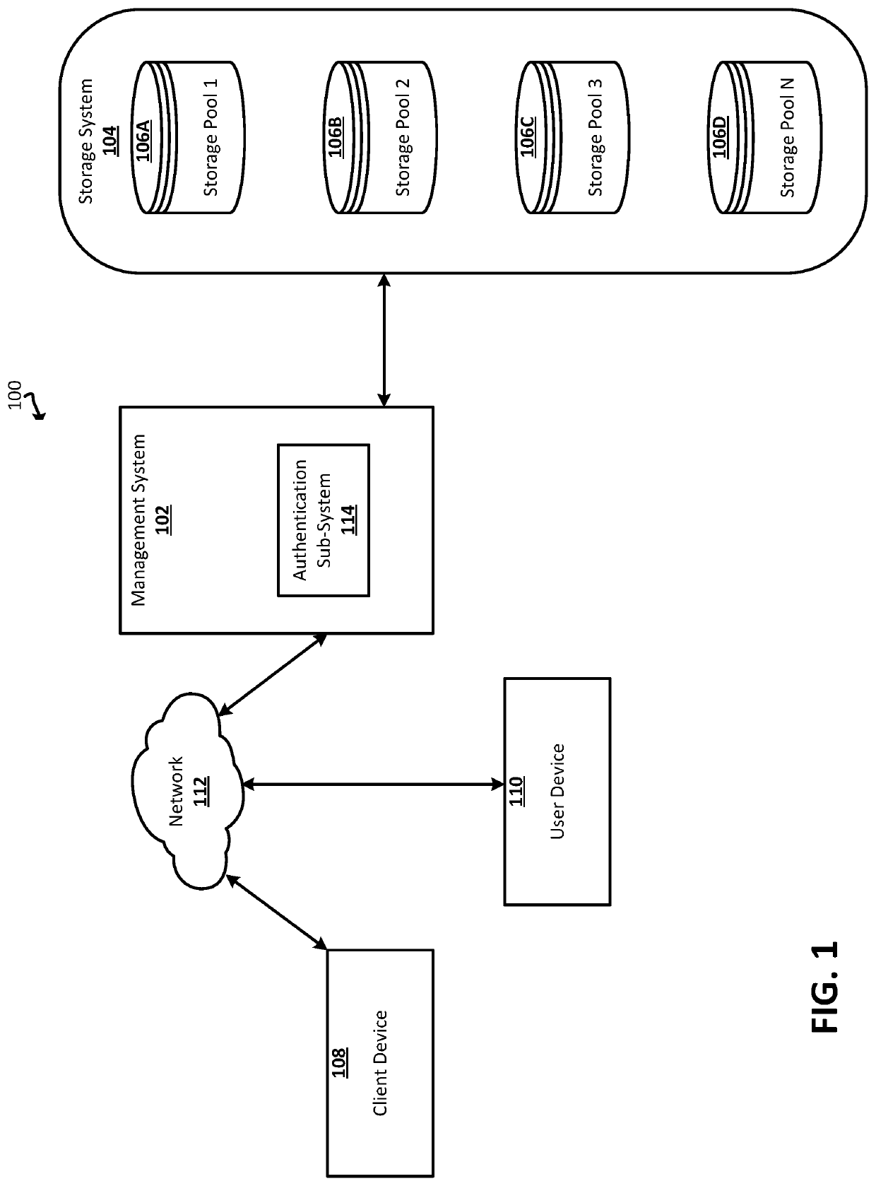
[0016]FIG. 1 is a simplified block diagram of an exemplary distributed environment 100. Distributed environment 100 may comprise multiple systems communicatively coupled to each other via one or more communication networks 112. The systems in FIG. 1 include one or more management systems 102, one or more storage systems 104, one or more client devices 108, and one or more user devices 110. Managem...


PUM


Abstract

A virtual storage device may be generated that replicates a layout of a physical storage device it is replacing. The virtual storage device may be used to store data formerly stored in the physical storage device. The layout may detail various configurations of the physical storage device such as if the physical storage derive implements fixed or variable-block sizes and / or if it implements a level of redundant array of independent disks (RAID). By replicating the layout of a physical storage device that it may replace, the virtual storage device described within various embodiments may offer advantages over other virtual storage devices.

Description

BACKGROUND[0001]Storage systems are the backbone of many Internet-based and cloud-based applications. Storage systems may store various datasets related to various applications and processes. Storage systems may include a plurality of storage devices, and these storage devices may be fallible. Whenever these storage devices fail, it may potentially compromise the storage system as a whole and thus any application or process that relies upon the storage system. Furthermore, storage capacity associated with a storage system may, in some instances, need to be reduced or repurposed. Embodiments described within this disclosure improve the performance of storage systems.BRIEF SUMMARY[0002]The present disclosure relates generally to storage systems. More particularly, techniques are described for replacing a physical storage device of a set of physical storage devices with a virtual storage device. More specifically, a virtual device can be defined to include a set of storage blocks (e.g....

Claims


Application Information

Patent Timeline
Patent Type & Authority Patents(United States)
IPC IPC(8): G06F3/06G06F11/34
CPCG06F3/065G06F11/3442G06F3/0689G06F3/064G06F3/0644G06F3/0607G06F3/0664G06F3/0683G06F11/2094G06F2201/815
Inventor JEYARAM, PRABAHARDING, YIMINLATUSHKIN, VICTORPODUSKA, JR., JOHN WILLIAM
Owner ORACLE INT CORP
Learn More