
Transfer chute to maintain a density of a flow of granular material

a technology of granular material and transfer chute, which is applied in the direction of chutes, transportation and packaging, etc., can solve the problems of uneven formation of granular materials, problems such as problems, and problems such as problems

Active Publication Date: 2020-08-25
UNIV OF MANCHESTER
View PDF32 Cites 1 Cited by
  • Summary
  • Abstract
  • Description
  • Claims
  • Application Information

AI Technical Summary

Problems solved by technology

Transfer of granular materials may be problematic.
Problems may arise when the granular material is formed by grains, granules or particles having two or a plurality of different sizes and / or densities.
Thus, at the outlet of the chute, the granular material is not formed by a uniform mixture of particle sizes i.e. the differently sized particles have separated within the chute.
Problems may also arise in that a flow of granular material through a chute may become one or both of fast and dilute, which may produce dust and chute wear.

Method used


Image

  • Transfer chute to maintain a density of a flow of granular material
  • Transfer chute to maintain a density of a flow of granular material
  • Transfer chute to maintain a density of a flow of granular material

Examples


Embodiment Construction

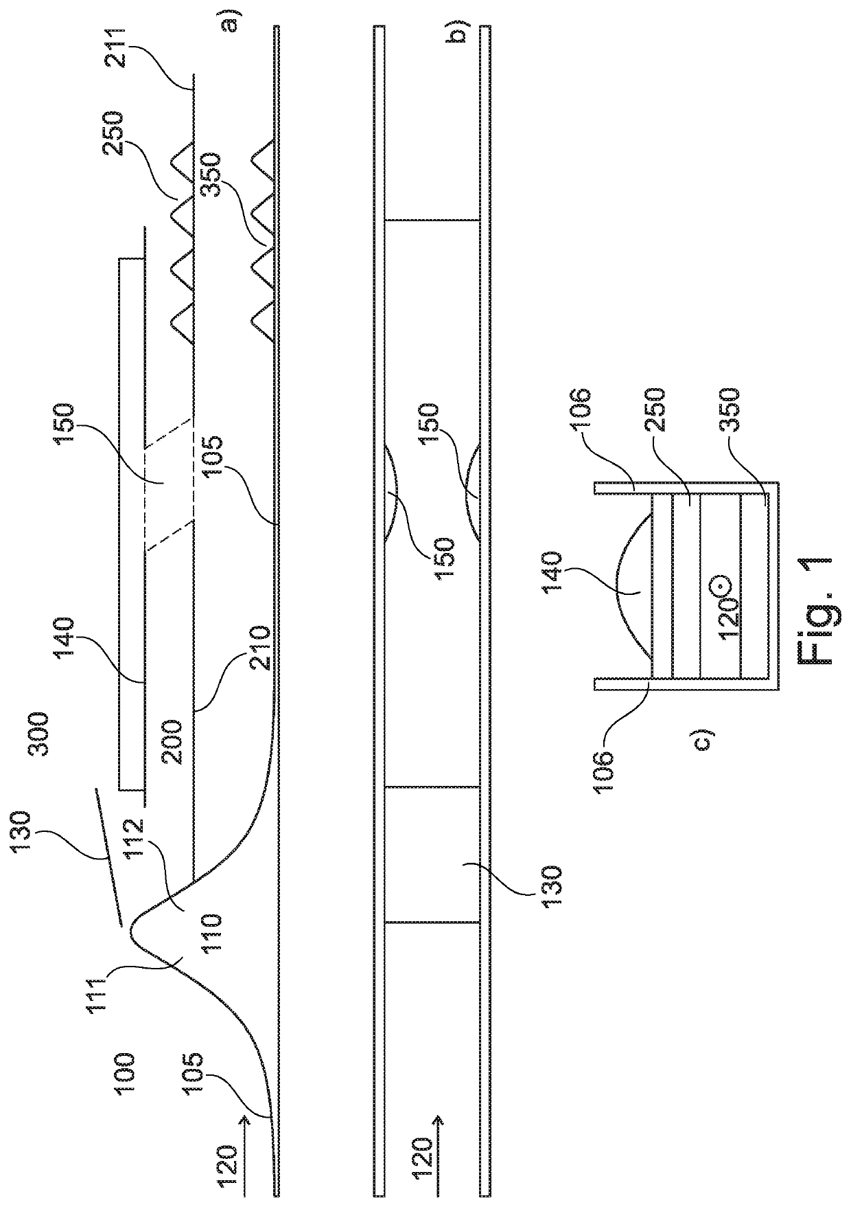
[0017]FIG. 1 illustrates a transfer chute, generally denoted as 100, according to an embodiment of the invention. FIG. 1(a) illustrates a longitudinal cross-section through the chute 100, FIG. 1(b) illustrates a top-down view of the chute 100 whilst FIG. 1(c) illustrates a lateral cross-section through the chute 100.

[0018]The transfer chute 100 includes a chute body which defines a flow pathway, as indicated by arrow 120 indicating a direction of flow, for granular material between an inlet and an outlet of the chute 100. The chute body has a bottom surface 105 first and second lateral side walls 106. Thus the chute may be U-shaped between the side walls 106, although it will also be appreciated that the chute may be enclosed by having a top surface in some embodiments. In use, the chute is inclined such that the outlet is lower than the inlet of the chute. The granular material flows under the influence of gravity, along the bottom surface 105 for at least a portion of the chute 10...


PUM


Abstract

The present invention relates to a transfer chute (100) for granular material, comprising a chute body defining a flow pathway (120) for granular material, a raised portion (110) having an inclined surface (111), and a splitter member (130) arranged proximal to the raised portion (110) for, in use, dividing a flow of granular material over the raised portion into first portion in first conduit (100) and a second portion in a second conduit (300). In some embodiments, a channel (150) is disposed between the first and second conduits (100; 300) to transpose a vertical arrangement of first and second portions of granular material within the chute (10). In this way, separation by particle size or density in the flow may be reversed.

Description

CROSS-REFERENCE TO RELATED APPLICATIONS[0001]This application is a National Phase of International Application No. PCT / GB2017 / 052216 filed Jul. 28, 2017, which designated the U.S. and that International Application was published under PCT Article 21(2) in English. This application also includes a claim of priority under 35 U.S.C. § 119(a) and § 365(b) to British patent application No. GB 1613068.4 filed Jul. 28, 2016, the entirety of which is hereby incorporated by reference.BACKGROUND[0002]It is known to transfer granular materials, such as powders or other particulate materials, via means of a transfer chute. A transfer chute is an inclined pathway between an inlet and outlet, wherein the pathway may be enclosed along part or all of its length. The inlet may receive granular material from a delivery point or an output of a process and transfer the granular material to an input of another process or an output point.[0003]Transfer of granular materials may be problematic. Problems m...

Claims


Application Information

Patent Timeline
Patent Type & Authority Patents(United States)
IPC IPC(8): B65G11/08B65G11/20
CPCB65G11/206
Inventor GRAY, JOHN MARK NICHOLAS TIMM
Owner UNIV OF MANCHESTER
Learn More