
Method and magnetic resonance apparatus for optimizing the simultaneous acquisition of magnetic resonance data from multiple slabs or slices

a technology of magnetic resonance data and optimizing simultaneous acquisition, applied in the direction of measuring using magnetic resonance, magnitude/direction of magnetic fields, instruments, etc., can solve the problems of insufficient representation of tissue with long t1 relaxation time, repetition time tr, etc., to increase the number of volume elements, facilitate signal separation, and increase the spatial separation of simultaneously excited volume elements

Active Publication Date: 2020-07-28
SIEMENS HEALTHCARE GMBH
View PDF6 Cites 0 Cited by
  • Summary
  • Abstract
  • Description
  • Claims
  • Application Information

AI Technical Summary

Benefits of technology

The present invention provides a procedure for simultaneous multislice imaging that improves image quality without compromising contrast. In typical simultaneous multislice imaging, there is a delay between processing of all the volume elements. The invention increases the number of volume elements for which MR data is acquired and improves signal separation, reducing noise. This reduces the number of averagings or oversampling in one of the phase encoding directions, reducing overall scan time while maintaining the original signal-to-noise ratio. The invention also optimizes the SMS factor based on the user's scan protocol. Additionally, the spacing between adjacent additional volume elements and the spacing between an additional volume element and a planned volume element adjoining it can be greater than the spacing between two adjacent planned volume elements, improving separation between volume elements and reducing g-factor noise. The invention is based on the fact that increasing the number of simultaneously excited volume elements improves image quality, especially with favorable system configurations having a lower density of receiving coil elements.

Problems solved by technology

For example, neither for T2-weighted imaging nor for imaging weighted according to proton density can the repetition time TR be selected too short, since otherwise tissue with long T1 relaxation times is not adequately represented.

Method used

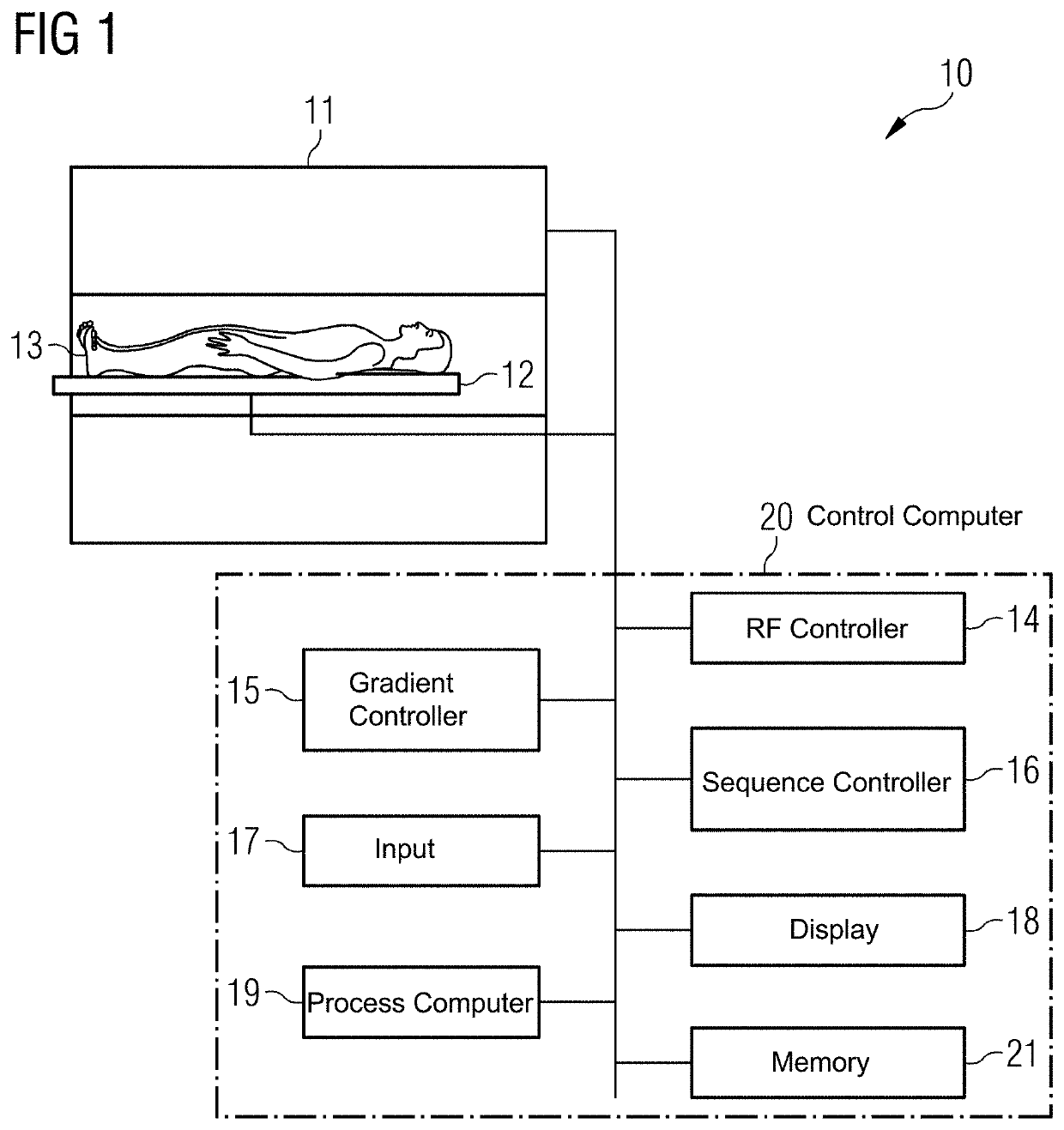
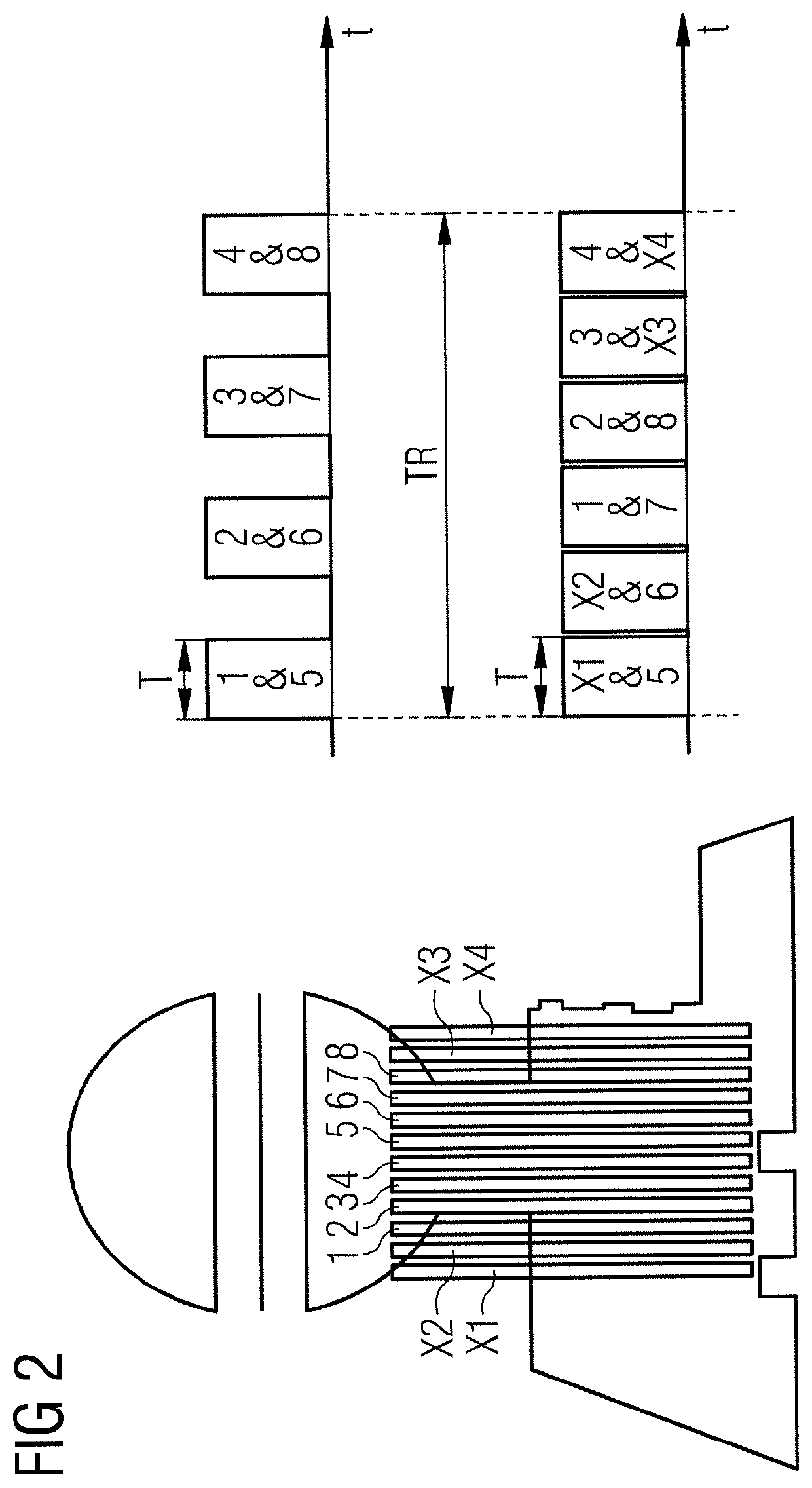

Image

  • Method and magnetic resonance apparatus for optimizing the simultaneous acquisition of magnetic resonance data from multiple slabs or slices
  • Method and magnetic resonance apparatus for optimizing the simultaneous acquisition of magnetic resonance data from multiple slabs or slices
  • Method and magnetic resonance apparatus for optimizing the simultaneous acquisition of magnetic resonance data from multiple slabs or slices

Examples


example 1

[0077]Example 1 has the following requirements or conditions:[0078]The number of planned slices is 16, which is sufficient for a complete coverage of the volume portion to be examined.[0079]The desired contrast requires a minimum repetition time TR of 3200 ms.[0080]The duration of a single echo train (TSE module) and thus the scan time T is 250 ms.[0081]For a complete MR image, 20 echo trains are required.[0082]In order to achieve a sufficiently large signal-to-noise ratio, 5 averagings are needed.

[0083]In a conventional single-layer imaging process, a real repetition time TRreal=250 ms*16=4000 would result, from which the total scan time of 5*20*4000 ms=6:40 minutes results.

[0084]In a conventional multi-slice imaging process with an SMS factor of 2, the repetition time could be TR=250 ms*16 / 2=2000 ms. Since, however, the minimum repetition time TR is 3200 ms, the real repetition time corresponds to this predetermined minimum repetition time. On the basis of the small slice spacing ...

example 2

[0087]Example 2 has the following requirements or conditions:[0088]The number of planned slices is 10.[0089]The minimum repetition time TR is 2000 ms.[0090]The duration of a single echo train (TSE module) and thus the scan time T is 200 ms.[0091]For a complete MR image, 20 echo trains are required.[0092]2 is given as the SMS factor.

[0093]Since with the number of planned slices at 10, the repetition time TR of 2000 ms, the scan time T of 200 ms and the SMS factor of 2, the inequality (1) defined above is fulfilled, the SMS factor is decremented. Since the new or decremented SMS factor is 1, it need not be further checked whether the inequality (1) also applies for the new SMS factor. Rather, the 10 planned slices are acquired conventionally, i.e. with a single slice imaging process. By this means, additional noise (“g-factor noise”) and deconvolution artifacts are prevented.

example 3

[0094]Example 3 has the following requirements or conditions:[0095]The number of planned slices is 12.[0096]The minimum repetition time TR is 2800 ms.[0097]The duration of a single echo train (TSE module) and thus the scan time T is 400 ms.[0098]3 is given as the SMS factor.

[0099]Since with the number of planned slices at 12, the repetition time TR of 2800 ms, the scan time T of 400 ms and the SMS factor of 3, the inequality (1) defined above is fulfilled, the SMS factor is decremented. Since the above inequality (1) for the new SMS factor 2 no longer applies, the MR data is acquired with the SMS factor 2. Since the number of all slices according to equation (3) is 14, in addition to the 12 planned slices, 2 additional slices are acquired.

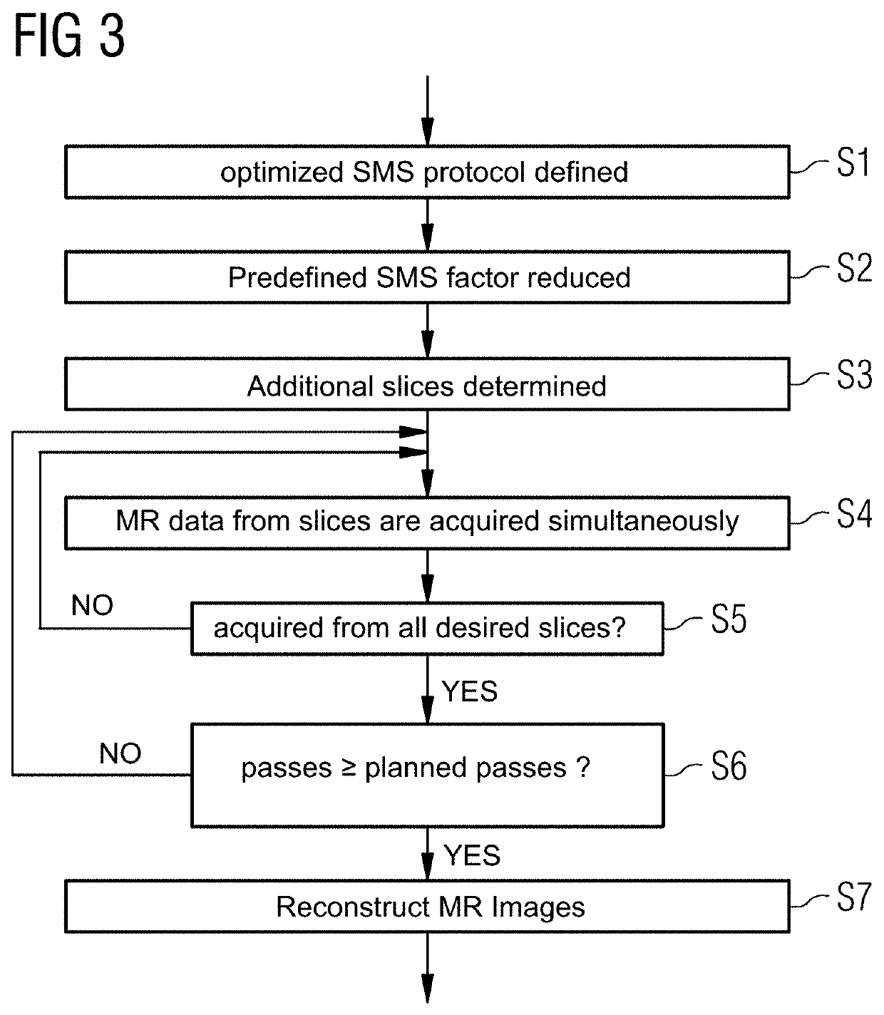
[0100]FIG. 3 shows a flowchart for the inventive method.

[0101]In step S1, the user defines for his requirements (contrast and slice coverage) an optimized SMS protocol in that the number of planned slices, the repetition time TR, the scan time T an...


PUM


Abstract

In an acquisition of magnetic resonance (MR) data from a volume portion of an object, a set of a number of planned volume elements is predefined in the volume portion, wherein MR data are to be acquired from each of the planned volume elements. Furthermore, conditions that are to be fulfilled in the acquisition of the MR data of the planned volume elements are predefined. Dependent upon the planned volume elements and the conditions, a set of additional volume elements is determined. The MR data are acquired from at least two volume elements simultaneously, the at least two volume elements including one volume element from the set of the planned volume elements and one volume element from the set of the additional volume elements.

Description

BACKGROUND OF THE INVENTIONField of the Invention[0001]The present invention concerns optimization with regard to the simultaneous acquisition of MR data from a number of volume elements (slabs or slices) of a subject.Description of the Prior Art[0002]The desire for ever faster MR recordings (data acquisitions) in the clinical environment is leading to renewed development of methods in which a number of images (more exactly, MR data in a number of slabs or slices) are recorded simultaneously. In general, these methods can be characterized by, at least during a part of the scan (the step of MR data acquisition), the transverse magnetization of at least two slabs or slices is used simultaneously for the imaging process. These methods are also known as multislice imaging or slice multiplexing and are often also designated simultaneous multislice (SMS) imaging.[0003]In contrast to multislice imaging or slice multiplexing, in the conventional imaging of multiple slices, the signal (the M...

Claims


Application Information

Patent Timeline
Patent Type & Authority Patents(United States)
IPC IPC(8): G01R33/483G01R33/24G01R33/56G01R33/561
CPCG01R33/24G01R33/5608G01R33/4835G01R33/5611
Inventor FEIWEIER, THORSTEN
Owner SIEMENS HEALTHCARE GMBH
Learn More