Method and apparatus for visualizing a blood vessel

a blood vessel and visualization technology, applied in the field of blood vessel visualization, can solve the problems of inability to determine the position and length of the thrombosis, and the procedure is comparatively expensive and time-consuming, so as to minimize the patient's exposure to x-rays, and reduce the risk of thrombosis

Active Publication Date: 2020-06-23
SIEMENS HEALTHCARE GMBH
View PDF9 Cites 2 Cited by
  • Summary
  • Abstract
  • Description
  • Claims
  • Application Information

AI Technical Summary

Benefits of technology

[0016]In another act, a data capture area for the acquisition of a further image data set is designated. The data capture area is smaller than the data capture area for the first volume data set. The second volume data set therefore includes only an extract from the spatial area covered by the first volume data set. The purpose of this procedure includes minimizing the patient's exposure to X-rays through this second data capture. The data capture area for the second volume data set is selected so as to provide that the entire area around the thrombosed section of the blood vessel (e.g., the entire thrombus) is included. For this purpose, the data capture area may be selected such that the size thereof is essentially determined from the length of the expected thrombus. For example, provision may be made for size definition (e.g., a diameter or a length) of the data capture area to be selected such that this is essentially (e.g., over 50%) determined by the length of the expected thrombus. The data capture area is therefore placed in a targeted manner in or around the area of the thrombus.
[0017]In another act, the acquisition of the second volume data set ensues. This may be achieved by, for example, computed tomography (CT), magnetic resonance tomography (MRT) or by C-arc-based imaging (e.g., capture of a further C-arm CT data set). The capture of the second image data set therefore ensues in a targeted manner in the previously defined data capture area, which contains the thrombus. The capture of the second image data set therefore ensues in a targeted manner in the area of the thrombus (e.g., within an area with a volume that is smaller than the volume of the area for the first image data set). In a targeted manner, it is therefore only the area of the thrombus that is irradiated or captured. For this purpose, the patient may be re-centered accordingly (e.g., arranged in the isocenter of the imaging device). A corresponding collimation is carried out. Alternatively, an asymmetrical collimation may be carried out during the acquisition of the 3D image, which renders the repositioning of the patient unnecessary. In the second volume data set, the entire vessel including the thrombosed section (e.g., obstructed section) of the vessel is visible. The image data set therefore contains an image of the course of the blood vessel in the area of the thrombus. For this purpose, there ensues an appropriate selection of the imaging and / or display parameters through which a good contrast may likewise be achieved in the area of the thrombosed section of the blood vessel. The imaging may not be based on contrasting achieved with a contrast agent, which would not show the obstructed section of the blood vessel that is desired. For representing the thrombus, “Dual Energy Imaging”, for example, may be selected. This is a procedure that is basically known and makes it possible to differentiate between different materials. The procedure involves irradiating the areas of interest with different energies (e.g., X-ray beam energies). Because the data capture area is restricted to the direct surroundings of the thrombosed section of the blood vessel, the patient's exposure to radiation may be minimized.
[0021]With the representation method according to one or more of the present embodiments, a thrombectomy may be achieved in a particularly safe and reliable manner.
[0025]Accordingly, the second volume data set may be a non-contrasted volume data set. In this way, the patient is not exposed to additional contrast agent through this additional scan, so that the method is advantageous, for example, with respect to “multimorbid” patients (e.g., with kidney problems, etc.). Restriction to the direct area or to the direct surroundings of the thrombus provides that exposure to radiation is reduced. The locating of the thrombus in the patient's vascular system is provided with the preceding first scan (e.g., first volume data set), which may be required anyway for imaging the vascular system.
[0029]The capture of the second volume data set may be provided in a targeted manner in the defined data capture area. This is to be understood, for example, as providing that the X-ray beams are directed in a targeted manner at the second data capture area, such that adjacent areas (e.g., along the longitudinal axis of the patient) are hardly exposed or not exposed to radiation. The isocenter of the imaging device (e.g., irradiation device, X-ray device) may be set in the midpoint of the data capture area. Restricting the irradiated area in the acquisition of the 3D scan to the virtual ball provides that exposure to radiation is extremely low.

Problems solved by technology

This may lead to considerable negative effects (e.g., to a further obstruction in the distal vascular area).
Due to the vascular obstruction by the thrombus, however, the contrast agent stops at the proximal end of the thrombus, such that it may not be possible to determine the position and length of the thrombus.
However, this procedure is comparatively expensive and time-consuming.
Within the thrombus, the physician has to navigate “blind”, however, so that there is a high risk of vascular injury (e.g., of perforation).
Since the thrombectomy device to be used (e.g., a stent retriever) may be aligned as much as possible with the length of the thrombus, the image does not make the physician aware of the optimum length of the device to be used.
Too short a stent retriever leads to the aforementioned problems.
An unnecessarily long stent retriever leads to increased difficulties in navigating through the vascular system and consequently increases the risk of vascular injury.

Method used


Image

  • Method and apparatus for visualizing a blood vessel
  • Method and apparatus for visualizing a blood vessel

Examples


Embodiment Construction

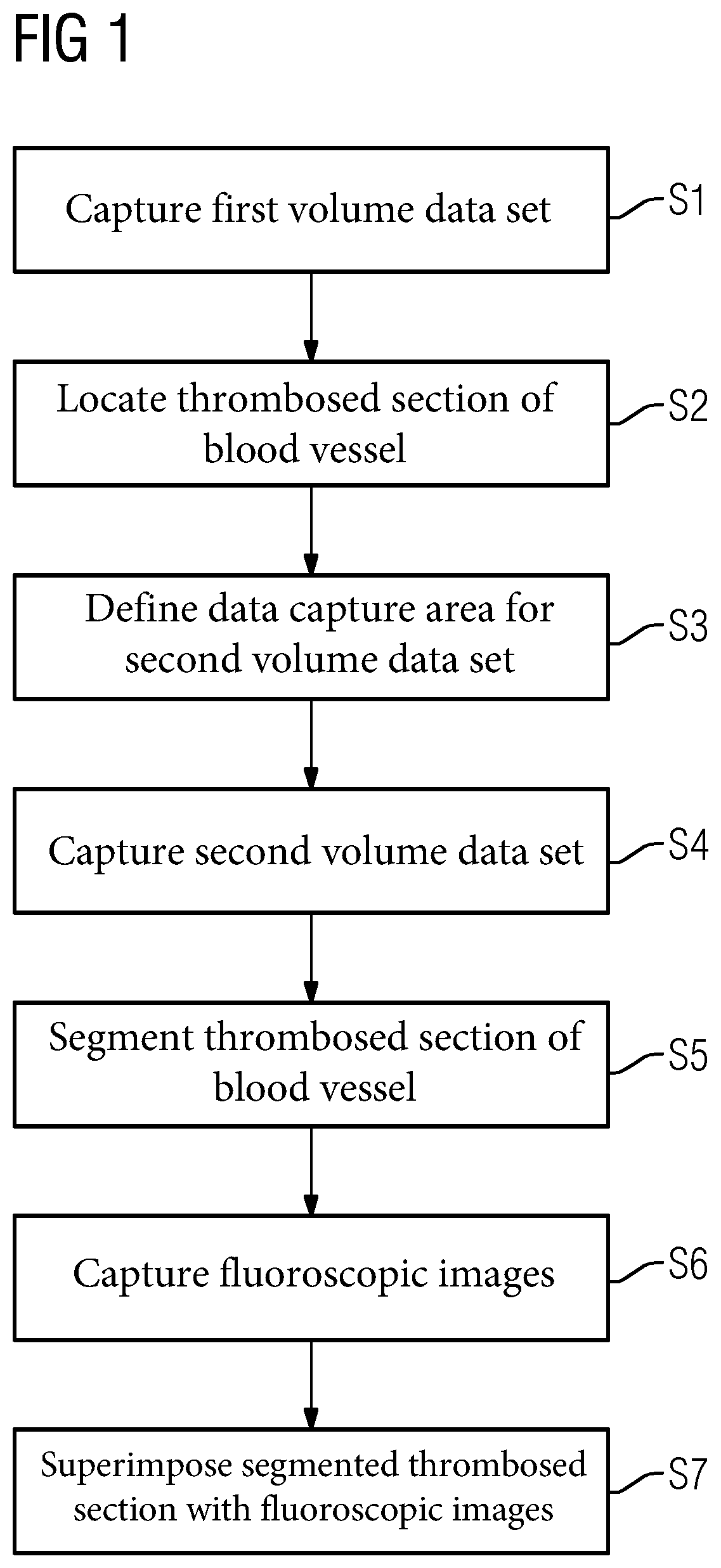
[0036]The individual process acts according to an embodiment of the method are described hereinafter with the aid of FIG. 1.

[0037]In act S1 (e.g., capture of a first volume data set), a first volume data set (e.g., image data set) is first acquired (e.g., pre-interventionally). The first volume data set is used to represent a “map” of the vascular system. For this purpose, a medical acquisition device (e.g., a computer tomograph, a magnetic resonance device or a C-arm device) may be used. Contrasted projected images are captured from different projection directions and reconstructed with an image reconstruction into a spatially three-dimensional volume data set, in a basically known manner. In the volume data set, the vessels may be recognized particularly well due to the contrasting using contrast agent. The imaging may ensue using the principle of digital subtraction angiography (e.g., a “native image” is subtracted from the contrast agent-contrasted X-ray image).

[0038]Using the f...


PUM


Abstract

A method for representing a blood vessel including a thrombosed section of the blood vessel in a patient is provided. The method includes capturing a first volume data set after administration of a contrast agent, locating a proximal and / or distal end of the thrombosed section of the blood vessel with the aid of the first volume data set, and defining a data capture area for a second volume data set based on the proximal and / or distal end of the thrombosed section of the blood vessel that has been located. The method also includes capturing the second volume data set, segmenting the thrombosed section of the blood vessel from the second volume data set, capturing fluoroscopic images, and superimposing the segmented thrombosed section of the blood vessel with the fluoroscopic images.

Description

[0001]This application claims the benefit of DE 10 2014 204 799.4, filed on Mar. 14, 2014, which is hereby incorporated by reference in its entirety.BACKGROUND[0002]The present embodiments relate to a method and an apparatus for representing a blood vessel including a thrombosed section of a blood vessel of a patient.[0003]A thrombosis is a vascular disease in which a blood clot (e.g., thrombus) forms in a blood vessel and partially or completely obstructs the blood vessel. Thrombi may appear in any blood vessel. In ischemic stroke, which is the most common form of stroke, a thrombus obstructs an artery. The thrombus leads to reduced perfusion of the supply area located at the distal end.[0004]To treat vascular diseases (e.g., thrombosis), it is a known procedure to insert a mini-catheter into the patient's vascular system in order to dissolve or remove the thrombus. A current method is “mechanical thrombectomy” using a “stent retriever”. This involves guiding the stent retriever th...

Claims


Application Information

Patent Timeline
Patent Type & Authority Patents(United States)
IPC IPC(8): A61B6/00
CPCA61B6/481A61B6/487A61B6/5235A61B6/504A61B6/5217A61B6/482A61B6/4441G16H50/30
Inventor LAUTENSCHLÄGER, STEFAN
Owner SIEMENS HEALTHCARE GMBH
Why Eureka
Try Eureka