
Portable image capture device having handle assembly disposed on main body and portable image capture system using such portable image capture device

a portable image capture and handle technology, applied in the field of portable image capture devices and portable image capture systems, can solve the problems of time-consuming systemic operation, poor readability of mobile phones, and inability to adjust parameters, so as to reduce the burden on the wrist, simplify and reduce the components of the portable image capture devices, the effect of saving the parameter adjustment tim

Active Publication Date: 2020-06-16
AVISION
View PDF23 Cites 1 Cited by
  • Summary
  • Abstract
  • Description
  • Claims
  • Application Information

AI Technical Summary

Benefits of technology

[0012]In summary, this disclosure utilizes the main body of the portable image capture device to concentrate the light source inside the main body, so that the image under the bottom side of the main body is fully illuminated. In the process of capturing images of multiple packages, the lighting environment in the main body is stable and single. As long as the optimum exposure of the light ray of the first package is determined, the images of the subsequent packages can be continuously captured according to the parameters of the first package or with minor parameter adjustments being performed, thereby saving the parameter adjustment time. The handle and the start button are disposed on the main body, so that the user can operate the portable image capture device with one single hand. The main work of processing information is performed by the computer or server disposed outside the electronic device, so that the components and weights of the portable image capture device can be simplified and reduced. Consequently, when the user manipulates the portable image capture device, the burden on the wrist is minimized. When the image data is transmitted to the electronic device, the electronic device can perform an optimal speed calculation and analysis and store the analyzed and identified data to the system. In this manner, this disclosure can effectively reduce the manpower and time required for preparing the paper document data into the electronic system, thereby achieving the objective of data systemization.

Problems solved by technology

Such the operation mode leads to the time-consuming systemic operation, and may also lead to a mistake caused by human error.
However, the mobile phone requires the user to spend time to determine where to capture the image, and the camera of the mobile phone is a zoom camera with an adjustable focal length, so that a period of focusing time is required upon image capturing.
In addition, the indoor image capturing effect of the mobile phone has the poor readability due to the insufficient light; and the outdoor image capturing effect of the mobile phone results in that the image content cannot be precisely analyzed and identified due to the over exposure or the reflective image.
Consequently, the user needs to spend a lot of time in fixing the position of the image and determining the focal length.
In addition, the light cannot be easily controlled, and the clarity of the captured image is not as good as expected.
When the original, such as a package, is large in volume, the original cannot be placed on the electronic device.
Meanwhile, such the electronic device has the large volume, and the user cannot carry the electronic device.
So, the problem that a large-scale electronic device is needed to perform the image capturing needs to be solved.

Method used


Image

  • Portable image capture device having handle assembly disposed on main body and portable image capture system using such portable image capture device
  • Portable image capture device having handle assembly disposed on main body and portable image capture system using such portable image capture device
  • Portable image capture device having handle assembly disposed on main body and portable image capture system using such portable image capture device

Examples


Embodiment Construction

[0022]The directional terms, such as up, down, left, right, front, rear and the like, mentioned in the following embodiments refer only to the directions of the accompanying drawings. Therefore, the used directional terms are intended to illustrate but not to limit this disclosure.

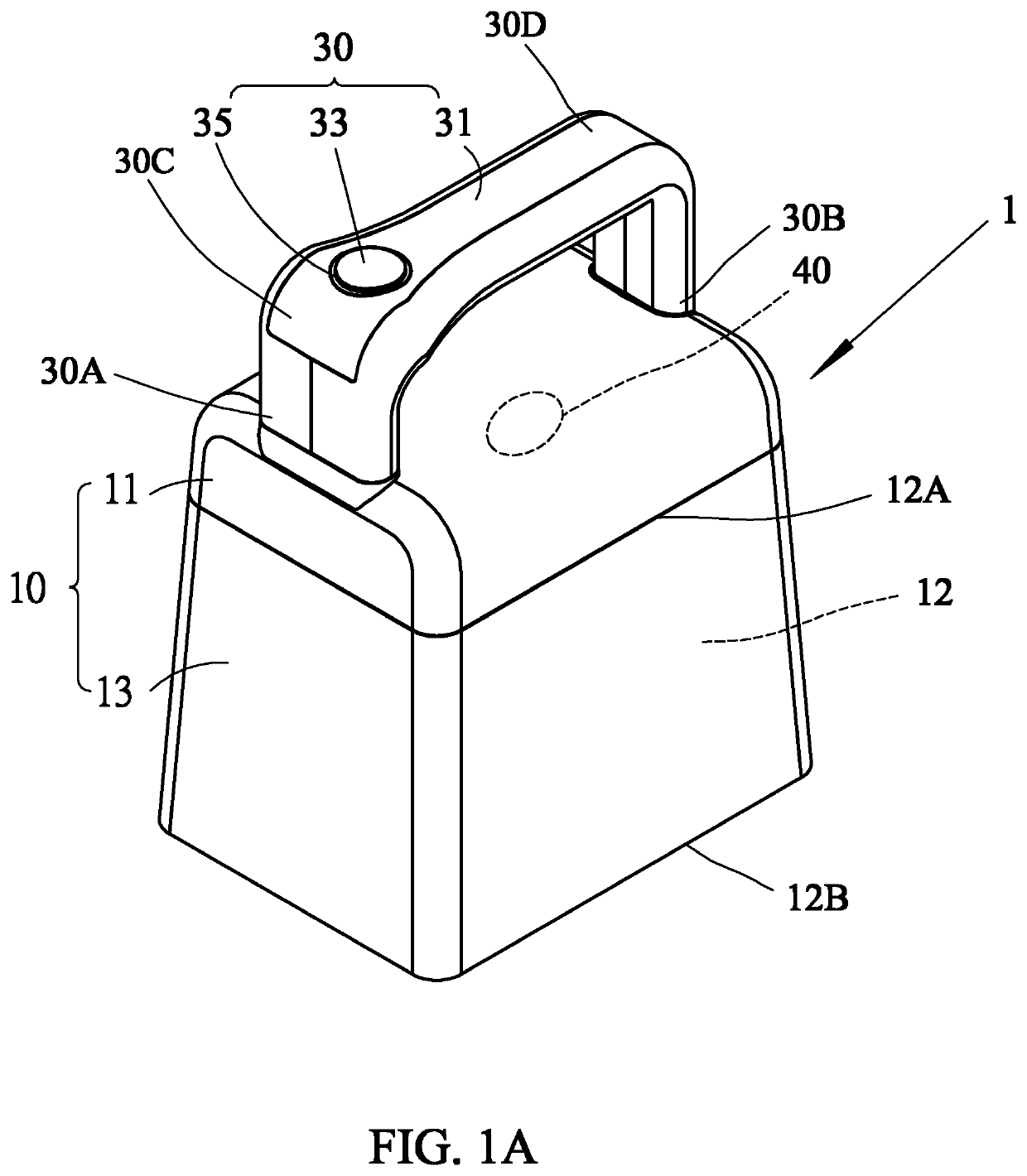
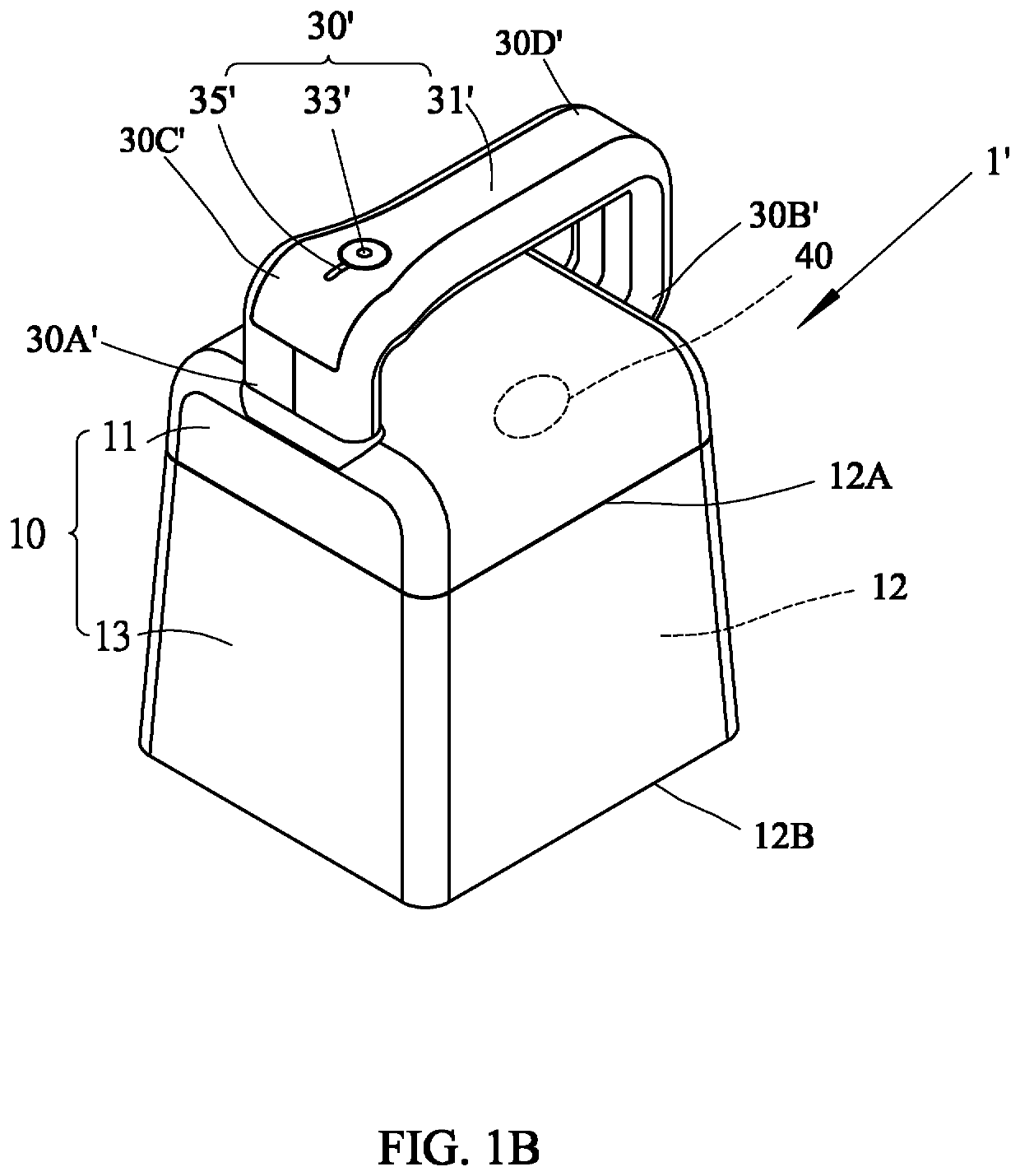
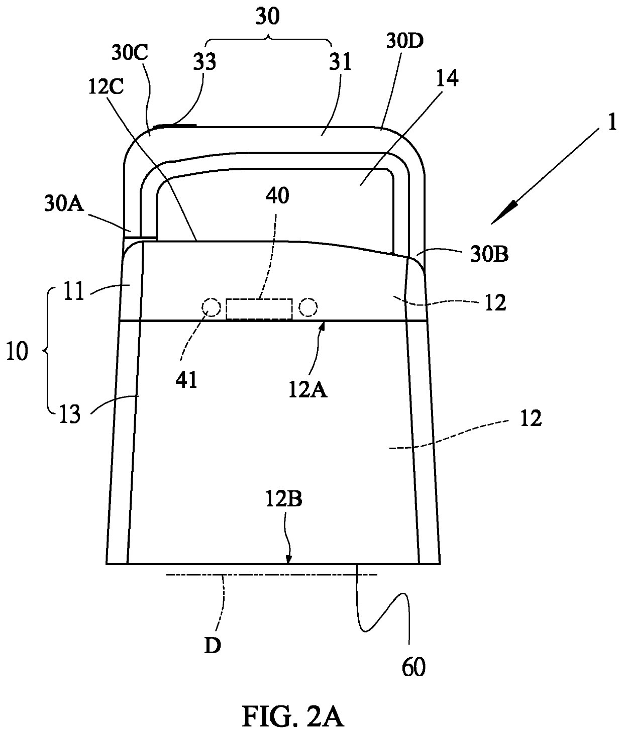
[0023]Please refer to FIGS. 1A and 1B. FIG. 1A is a schematic outlook view showing a portable image capture device 1 according to a first embodiment of this disclosure, and FIG. 1B is a schematic outlook view showing a portable image capture device 1′ according to a second embodiment of this disclosure. In FIG. 1A, the portable image capture device 1 includes a main body 10, an image capture assembly 40 (see also FIG. 4) and a handle assembly 30. The main body 10 includes a top side 12A, a bottom side 12B disposed opposite the top side 12A, and an internal space 12 disposed between the top side 12A and the bottom side 12B. The image capture assembly 40, which includes a complementary metal-oxide semiconduc...


PUM


Abstract

A portable image capture device includes a main body, an image capture assembly and a handle assembly. The main body includes a top surface, a bottom side disposed opposite the top surface, and an internal space disposed between the top surface and the bottom side. The image capture assembly disposed in the internal space faces the bottom side and performs image capturing. The handle assembly includes a handle part and a start button disposed beside the handle part. The handle assembly is disposed on the main body, and the image capture assembly is separated from the handle assembly and disposed under the top surface and above the bottom side so that a user uses one single hand to operate the portable image capture device and control image capturing timings.

Description

CROSS-REFERENCE TO RELATED APPLICATIONS[0001]This application claims priority of No. 107100148 filed in Taiwan R.O.C. on Jan. 3, 2018 under 35 USC 119, the entire content of which is hereby incorporated by reference.BACKGROUND OF THE INVENTIONField of the Invention[0002]This disclosure relates to a portable image capture device and a portable image capture system using the same, and more particularly to a portable image capture device including an image capture assembly and a handle assembly disposed on a main body, and a portable image capture system using the portable image capture device.Description of the Related Art[0003]Existing types of bills include bills of exchange, checks, promissory notes and the like. The forms of bills issued by different banks are also different. The contents are nothing more than the bill holder, payee, drawer, designated payer, amount, currency and the like. For the bank that receives the bill, in order to achieve the purpose of data induction and a...

Claims


Application Information

Patent Timeline
Patent Type & Authority Patents(United States)
IPC IPC(8): G03B17/56G03B11/04H04N5/232G06K9/22H04N5/225G03B15/00G06K9/00
CPCG03B15/00G03B17/563G06K9/228H04N5/2252G03B11/045H04N5/23203G06K9/00442H04N5/2251H04N23/56H04N23/54H04N23/55H04N23/57H04N23/60G06V30/142H04N23/51H04N23/66H04N23/50
Inventor SHENG, SHAO-LAN
Owner AVISION
Learn More