Collision detection and avoidance

a technology of collision detection and avoidance, applied in the field of remote controlled piloting, can solve the problems of drone damage or complete destruction, drone damage, drone collision danger,

Active Publication Date: 2020-06-09
SONY COMPUTER ENTERTAINMENT INC
View PDF167 Cites 6 Cited by
  • Summary
  • Abstract
  • Description
  • Claims
  • Application Information

AI Technical Summary

Problems solved by technology

Drones are both expensive and fragile.
A collision, even at low speeds, can cause serious damage or complete destruction to the drone, from the initial impact or from the subsequent impact with the ground.
Even an experienced pilot, when performing high risk maneuvers, will put a drone in danger of collision.

Method used


Image

  • Collision detection and avoidance
  • Collision detection and avoidance
  • Collision detection and avoidance

Examples


Embodiment Construction

[0021]The subject disclosure provides techniques for collision detection and avoidance for unmanned aerial vehicles, in accordance with the subject technology. Various aspects of the present technology are described with reference to the drawings. In the following description, for purposes of explanation, numerous specific details are set forth in order to provide a thorough understanding of one or more aspects. It can be evident, however, that the present technology can be practiced without these specific details In other instances, well-known structures and devices are shown in block diagram form in order to facilitate describing these aspects. The word “exemplary” is used herein to mean “serving as an example, instance, or illustration.” Any embodiment described herein as “exemplary” is not necessarily to be construed as preferred or advantageous over other embodiments.

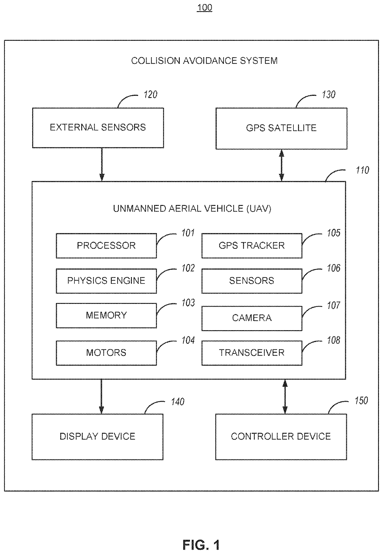
[0022]FIG. 1 illustrates a block diagram of an example collision avoidance system 100. The collision avoidance s...


PUM


Abstract

A collision avoidance system for an unmanned aerial vehicle (UAV) receives physical space data for a flight area and creates a virtual world model to represent the flight area by mapping the physical space data with a physics engine. The automatic collision avoidance system creates a virtual UAV model to represent the UAV in the virtual world model. The automatic collision avoidance system receives flight data for the UAV and determines a current position of the virtual UAV model within the virtual world model. The automatic collision avoidance system determines a predicted trajectory of the virtual UAV model within the virtual world model, and determines whether the predicted trajectory will result in a collision of the virtual UAV model with the virtual world model. The automatic collision avoidance system performs evasive actions by the UAV, in response to determining that the predicted trajectory will result in a collision.

Description

CROSS-REFERENCE TO RELATED APPLICATION[0001]This application claims the benefit of U.S. Provisional Patent Application Ser. No. 62 / 402,747 entitled “COLLISION DETECTION AND AVOIDANCE”, filed Sep. 30, 2016. The aforementioned application is herein incorporated by reference in its entirety.[0002]This application is related to U.S. Provisional Patent Application Ser. No. 62 / 402,752 entitled “STEERING ASSIST”, filed Sep. 30, 2016, and U.S. Provisional Patent Application Ser. No. 62 / 402,737 entitled “REMOTE CONTROLLED OBJECT MACRO AND AUTOPILOT SYSTEM”, filed Sep. 30, 2016, all of which are incorporated herein by reference.BACKGROUND OF THE INVENTION[0003]Field of the Invention[0004]This application relates to remote controlled piloting, and more particularly to a system and method for collision detection and avoidance for unmanned aerial vehicles.[0005]Description of the Related Art[0006]An unmanned aerial vehicle (UAV), commonly known as a drone or quadricopter, or by several other nam...

Claims


Application Information

Patent Timeline
Patent Type & Authority Patents(United States)
IPC IPC(8): G08G5/00G08G5/04B64C39/02B64D45/04G05D1/10G01C21/16
CPCG08G5/0021G08G5/0086B64D45/04G08G5/045G05D1/101B64C39/024G08G5/0069G01C21/16B64C2201/141G05D1/106B64U2201/10B64U50/39B64U10/14B64U50/23
Inventor KIKUCHI, MEGUMITAYLOR, MICHAELCASTLEMAN, DENNIS DALEYOUNG, ANDREW STEPHEN
Owner SONY COMPUTER ENTERTAINMENT INC
Why Eureka
Try Eureka