
Wear sensor and the corresponding wear element, assembly and use

a technology for wear sensors and wear elements, applied in the field of wear sensors, can solve the problems of wear sensors being subjected to very demanding working conditions, and achieve the effects of minimizing energy costs, maximizing field lines, and minimizing losses

Active Publication Date: 2020-06-09
METALOGENIA RES & TECH SL
View PDF17 Cites 2 Cited by
  • Summary
  • Abstract
  • Description
  • Claims
  • Application Information

AI Technical Summary

Benefits of technology

Enables accurate prediction of wear element replacement needs, reducing downtime and preventing damage by providing real-time wear data, even in harsh environments, and allowing for coordinated maintenance with existing machine shutdowns.

Problems solved by technology

In fact, the wear sensor will be subjected to very demanding working conditions, due to the environment characteristic of the wear element.

Method used


Image

  • Wear sensor and the corresponding wear element, assembly and use
  • Wear sensor and the corresponding wear element, assembly and use
  • Wear sensor and the corresponding wear element, assembly and use

Examples


first embodiment

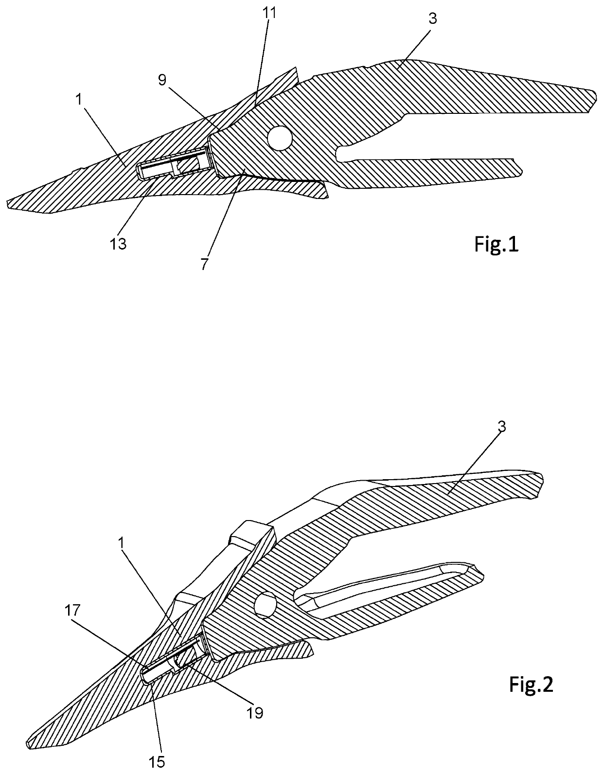
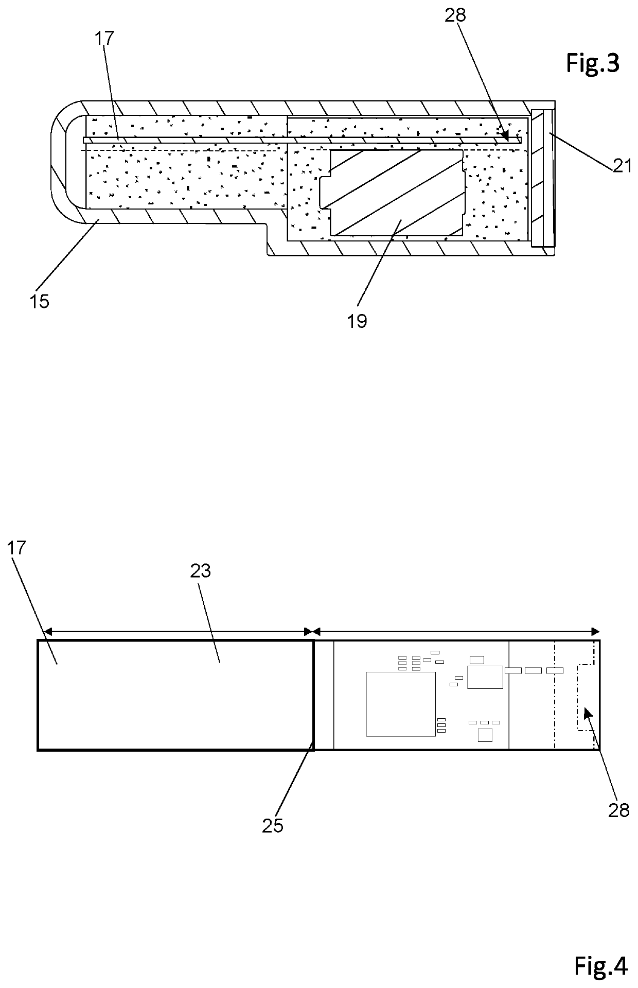
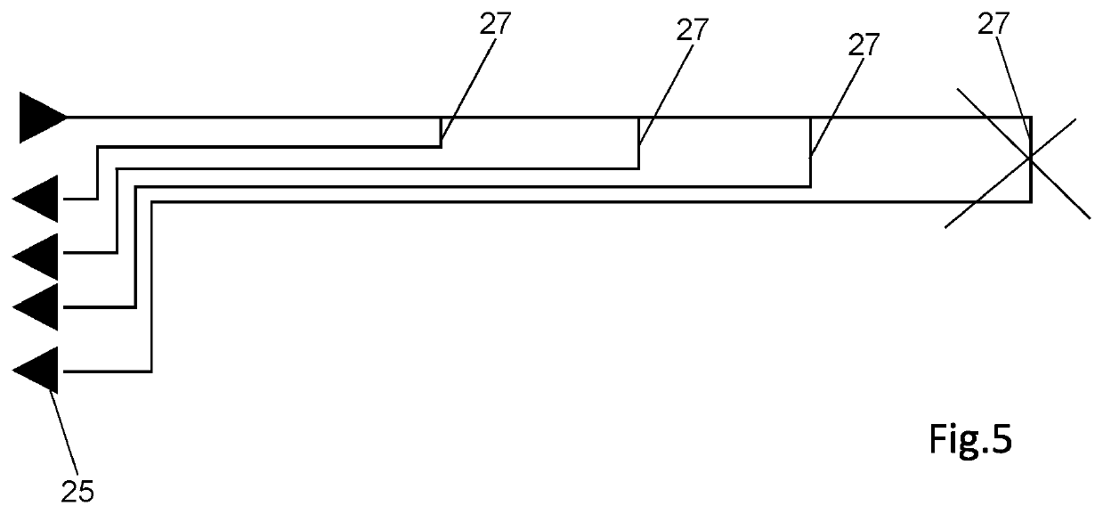
[0057]FIGS. 1 to 5 show the present invention. A tooth 1 is assembled on a conventional support or adapter 3 which is in turn suitable to be assembled on the lip of a shovel of an earth moving machine or the like (see FIG. 13). The tooth 1 is the wear element according to the present invention. The tooth 1 has in its rear end a housing in which a nose 7 located at the front end of the support 3 is housed. The housing has an inner surface 9 which, in the assembled position, will face an inner surface 11 of the nose 7. In the present description and claims it has been indicated that the inner surface 11 of the nose 7 is “inner” because it is isolated from the environment in the assembled position and not because it is a concave-type surface. In the case of the inner surface 9 of the housing of tooth 1, the term “inner” is also because the surface is isolated from the environment in the assembled position although, in the present case, it is also a convex surface. Therefore, in the cas...

second embodiment

[0064]FIGS. 6 to 12 show the present invention. In a manner similar to the preceding case, a tooth 1 is assembled on a support 3 which is in turn suitable for being assembled on the lip of an excavating bucket. However, in the present case the support 3 has a second opening 29 and the sensor is made up of two portions, which are two independent parts. The first portion 31 is housed in the opening 13 of the tooth 1 whereas the second portion 33 is housed in the second opening 29 of the support 3. Both openings 13 and 29 are facing one another in the assembled position so the first portion 31 and the second portion 33 are also facing one another in the assembled position.

[0065]The first portion 31 comprises the sensing electric circuit which, like in the preceding case, is formed by a substantially elongated printed circuit board defining the arm 23. In this case, instead of resistances arranged in parallel, the sensing electric circuit comprises a cascade of LC circuits. A plurality ...


PUM

PropertyMeasurementUnit
frequencyaaaaaaaaaa
frequencyaaaaaaaaaa
frequencyaaaaaaaaaa

Abstract

Wear sensor and the corresponding wear element, assembly and use. The sensor is intended for a wear element in a bucket of an earth moving machine. The sensor includes a sensing electric circuit and at least one elongated arm (23) extending in a direction of detection defining a longitudinal axis. The arm (23) has a base (25) and an end. The end wears away together with the wear material of the wear element. The arm (23) includes a plurality of electrical connections (27) forming part of the sensing electric circuit and extending different lengths with respect to one another, measured according to the longitudinal axis along the arm (23).

Description

FIELD OF THE INVENTION[0001]The invention relates to a wear sensor for a wear element in a bucket of an earth moving machine. It is also suitable for dredging vessels provided with cutting heads that excavate, transport and deposit material from submerged areas.[0002]The invention also relates to a wear element of a bucket of an earth moving machine with a sensor according to the invention as well as to an assembly formed by the mentioned wear element and the corresponding support or adapter, where the wear element has a rear end suitable for being assembled on the support and the support has a front end suitable for being assembled on the wear element, where the rear end of the wear element has an inner surface which, in the assembled position, is facing an inner surface of the front end of the support.[0003]The invention also relates to use of a wear sensor according to the invention.STATE OF THE ART[0004]Earth moving machines are used in excavation work, demolition work, construc...

Claims


Application Information

Patent Timeline
Patent Type & Authority Patents(United States)
IPC IPC(8): G01R31/00G01N3/56E02F9/26
CPCE02F9/264G01N3/56E02F9/267G01N2203/06E02F9/2816G01N2203/0664
Inventor MARQUEZ LLINAS, JORDICESAR GALOBARDES, JOANVALLVE, NILTRIGINER BOIXEDA, JORGETORAL MARTIN, CRISTIANPUIG CASTELLO, ALBERTCAMPRUBI TORRAS, ENRIC
Owner METALOGENIA RES & TECH SL
Learn More