Travel assistance device and travel assistance method using travel assistance device

a technology of assistance device and travel assistance, which is applied in the direction of instruments, television systems, image enhancement, etc., can solve the problem that the division line cannot be estimated

Active Publication Date: 2020-06-02
FUJIFILM CORP
View PDF31 Cites 1 Cited by
  • Summary
  • Abstract
  • Description
  • Claims
  • Application Information

AI Technical Summary

Benefits of technology

[0030]According to the travel assistance device of the present disclosure and the travel assistance method of the travel assistance device of the present disclosure, even in a case where the division line having an illuminance lower than the minimum illuminance of the visible imaging unit in the visible image cannot be detected on the basis of the pixel value of the visible image, the road end lines of the road on which the vehicle travels are detected from the infrared image, the division line of the road is detected from the visible image, and an integrated image indicating the road end lines and the division line is generated on the basis of the infrared image and the visible image registered with each other, and the extended portion of the division line in the integrated image is estimated on the basis of the division line and the road end line in the integrated image. Thus, it is possible to suitably estimate the extended portion of the division line.

Problems solved by technology

However, the technologies disclosed in JP04584277B, JP2001-101596A, JP2006-185406A, and JP2005-316607A cannot solve the above problem since the technologies are technologies for detecting a division line from a visible image on the basis of brightness and darkness of the pixel value of the visible image.
Further, according to the technology of JP2001-101596A, a travel road estimated without depending on information on an external environment such as a road or a division line is unclear in a relationship with the division line or the road, and the division line cannot be estimated on the basis of the travel road.

Method used


Image

  • Travel assistance device and travel assistance method using travel assistance device
  • Travel assistance device and travel assistance method using travel assistance device
  • Travel assistance device and travel assistance method using travel assistance device

Examples


first embodiment

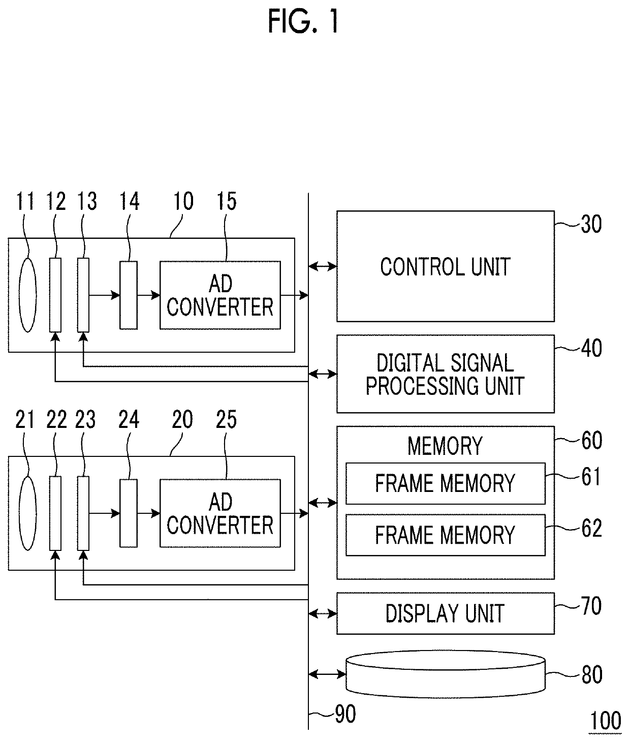
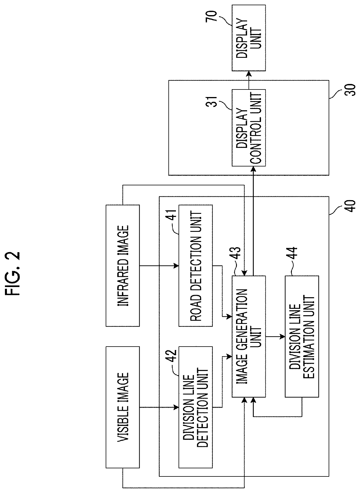
[0057]FIG. 2 is a block diagram illustrating a configuration of the digital signal processing unit 40 and the control unit 30 in the In each embodiment of the present specification, the control unit 30 functions as a display control unit 31 for controlling a display of the display unit 70 by executing a program that defines the travel assistance process according to this embodiment stored in the memory 60.

[0058]The digital signal processing unit 40 functions as a road detection unit 41 that detects a road end line of a road on which a vehicle travels from the captured infrared image, a division line detection unit 42 that detects a division line of the road from the captured visible image, an image generation unit 43 that generates an integrated image indicating the road end lines and the division line on the basis of the infrared image and the visible image registered with each other, and a division line estimation unit 44 that estimates an extended portion of the division line in...

second embodiment

[0116]In view of the above, in the second embodiment, even in a case where there is an object that is detected from the infrared image and cannot be detected in the visible image, the travel lane area of a subject vehicle is set using the estimated extended portion of the division line, the presence or absence of an object which may be an obstacle in the travel lane area is determined, and in a case where there is an object which may be an obstacle, a warning is issued for a user such as a driver.

[0117]FIG. 9 is a block diagram illustrating a configuration of a digital signal processing unit 40 and a control unit 30 in the second embodiment. In each embodiment below, the same configurations as those of the first embodiment are denoted with the same reference numerals, and description thereof will be omitted.

[0118]The second embodiment is different from the first embodiment in that the travel assistance device 100 further includes an area setting unit 45, an object detection unit 46,...

third embodiment

[0159]Next, a flow of a process of the travel assistance device 100 of the third embodiment will be described with reference to FIG. 14. Since ST61 to ST64, ST65 (in the case of YES), ST66 and ST67 are the same processes as those of ST01 to ST07 in FIG. 6, description thereof will be omitted.

[0160]In a case where the extended portion of the division line is estimated, the area setting unit 45 sets the travel lane area (ST68). The exposure correction unit 48 calculates the most frequent value of the pixel value of the travel lane area using a pixel value histogram of the travel lane area. Using the calculated most frequent value as an evaluation value, an exposure parameter of the visible image corresponding to the evaluation value is set. The exposure correction of the visible image is performed using the set exposure parameter, and a visible image after processing is output (ST69).

[0161]Subsequently, the image generation unit 43 generates a display image on the basis of the process...


PUM


Abstract

Present disclosure provides a travel assistance device which comprises: a road detection unit that obtains an infrared image in front of a vehicle from an infrared imaging unit that is mounted on the vehicle, and detects a road end line of a road on which the vehicle travels from the captured infrared image; a division line detection unit that obtains a visible image in a range corresponding to a range indicated by the infrared image from a visible imaging unit that is mounted on the vehicle, and detects a division line of the road from the captured visible image; an image generation unit that generates an integrated image indicating the road end line and the division line on the basis of the infrared image and the visible image registered with each other; and a division line estimation unit.

Description

CROSS-REFERENCE TO RELATED APPLICATIONS[0001]This application is a continuation application of International Application No. PCT / JP2016 / 004052, filed Sep. 6, 2016, the disclosure of which is incorporated herein by reference in its entirety. Further, this application claims priority from Japanese Patent Application No. 2015-179506 filed on Sep. 11, 2015, the disclosure of which is incorporated herein by reference in its entirety.BACKGROUNDTechnical Field[0002]The present disclosure relates to a travel assistance device that assists in traveling of a vehicle and a travel assistance method using the travel assistance device, and more particularly, to a travel assistance device that assists in traveling of a vehicle on the basis of an infrared image captured by an infrared imaging unit mounted on a vehicle, and a visible image captured by a visible imaging unit mounted on the vehicle, and a travel assistance method using the travel assistance device.Related Art[0003]In the related art, ...

Claims


Application Information

Patent Timeline
Patent Type & Authority Patents(United States)
IPC IPC(8): H04N5/232G06K9/20G06T7/174H04N5/33B60R1/00H04N5/272G06K9/00H04N7/18G08G1/0962G08G1/16G06T7/12G06K9/62G06V10/143
CPCB60R1/00G06K9/00798G06T7/174H04N5/33G06K9/00805H04N7/18G08G1/166H04N7/183G08G1/0962G06T7/12G06K9/00369G08G1/167G06K9/2018B60R2300/307G06T2207/10048B60R2300/108G06T2207/30256G06K9/6293B60R2300/804G06T2207/10024G06V40/103G06V20/588G06V20/58G06V10/143G06F18/256
Inventor FUJIKAWA, TETSUYA
Owner FUJIFILM CORP
Why Eureka
Try Eureka