Computer system

a computer system and computer technology, applied in the field of computer systems, can solve the problems of increasing the complexity of managing a data store, unable to efficiently obtain data, and user inability to judge which data store he/she should obtain data

Active Publication Date: 2020-05-26
HITACHI LTD
View PDF21 Cites 0 Cited by
  • Summary
  • Abstract
  • Description
  • Claims
  • Application Information

AI Technical Summary

Benefits of technology

[0008]An object of the present invention is to provide a system and a method by which it is possible to identify an appropriate data store and obtain data from the data store without the user needing to know attributes of data stored in the data store, and in particular, time attributes.

Problems solved by technology

This has meant that data could not be obtained efficiently.
However, constructing a data store for each aggregation process would increase the complexity of managing a data store.
Thus, the user cannot judge which data store he / she should obtain the data from.
According to the technique disclosed in JP H8-83206 A, it is possible to obtain data from a plurality of databases or non-databases that manage different types of data, but data cannot be obtained efficiently in a computer system that requires complex data management.
Also, the user needs to know in advance the attributes of data stored in the data store, but it would be difficult to know the attributes of the data stored in the data store in a computer system having a plurality of data stores that are dynamically updated and manage a plurality of pieces of data for each aggregation process.

Method used


Image

  • Computer system
  • Computer system
  • Computer system

Examples


embodiment 1

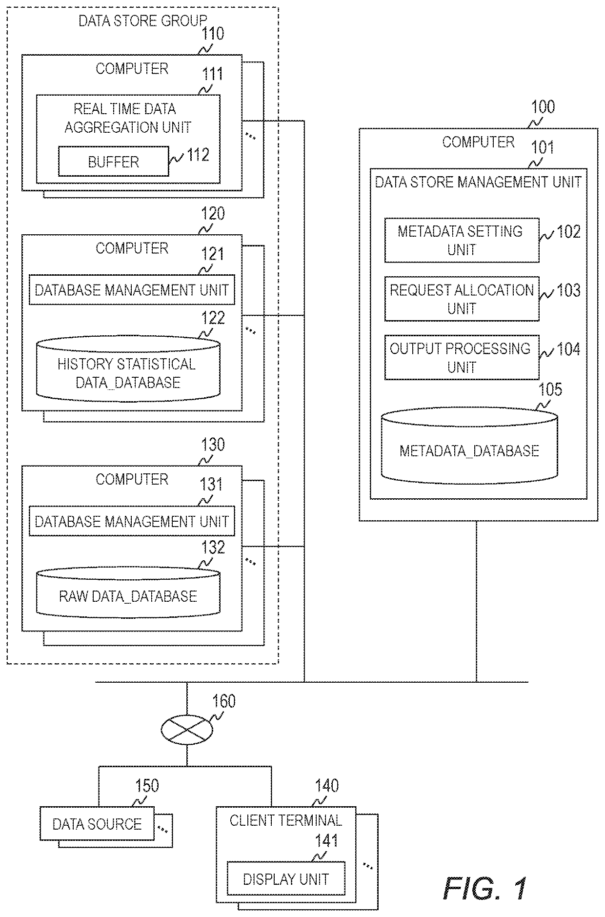
[0029]FIG. 1 is a block diagram for showing a configuration example of a computer system of Embodiment 1.

[0030]The computer system includes a plurality of computers 100, 110, 120, and 130 and a plurality of client terminals 140.

[0031]The computer 100, the plurality of computers 110, the plurality of computers 120, the plurality of computers 130, and the plurality of client terminals 140 are connected to each other through a network 160. The network 160 may take any form as long as it enables communication between the computer 100, the plurality of computers 110, 120, and 130, and the plurality of client terminals 140. The network type may be a WAN, a LAN, or the like, and the network connection mode may be wireless or wired, for example.

[0032]The client terminal 140 is a computer used by the user, and has hardware such as a processor (not shown), memory (not shown), and a network interface (not shown). The client terminal 140 runs a display unit 141 for displaying data and the like ...

embodiment 2

[0199]In Embodiment 2, the process of a data store management unit 101 will be described for a case in which a new real time aggregation process is added. Below, the description of Embodiment 2 will center on differences from Embodiment 1.

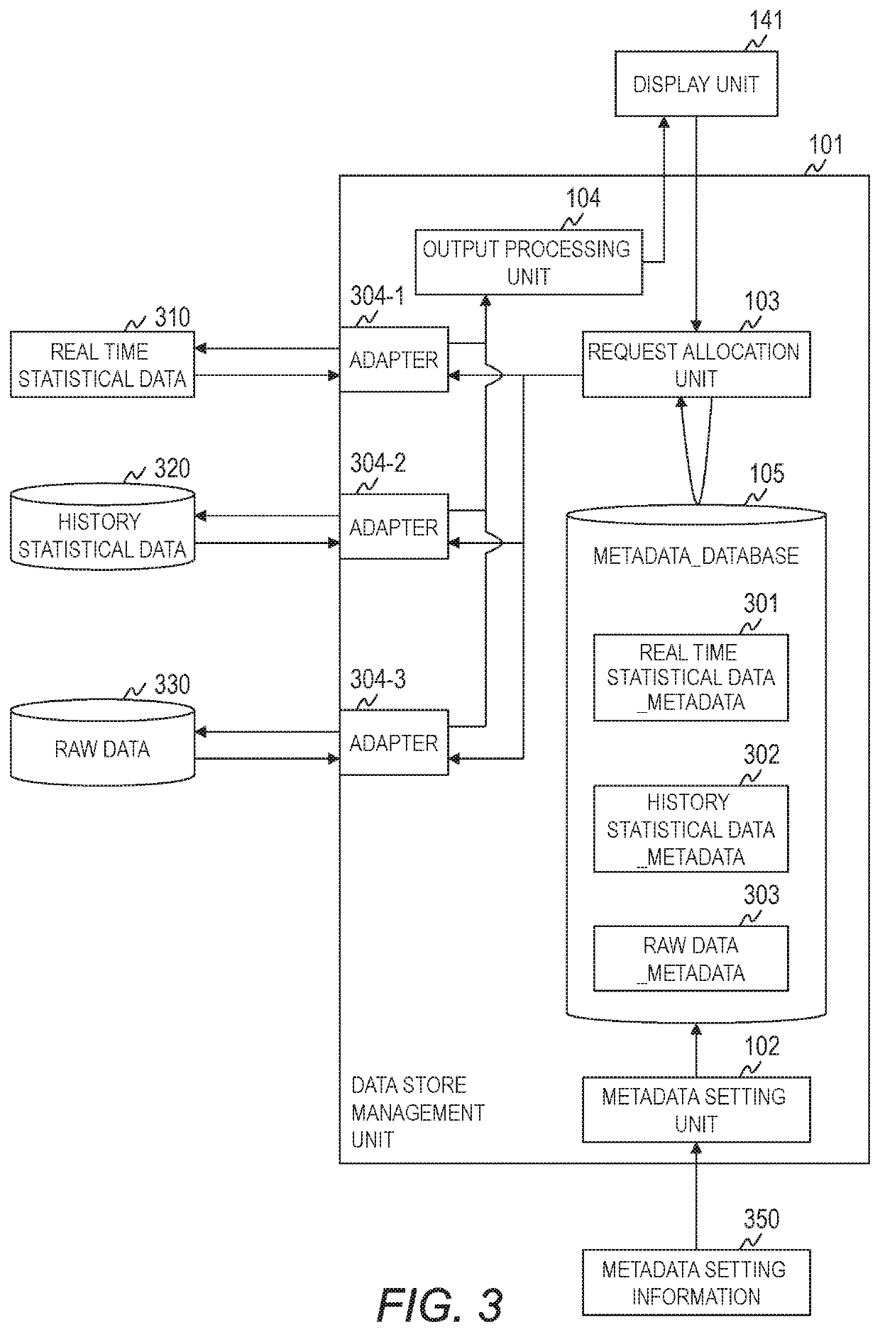
[0200]The configuration of the computer system and the hardware and software configurations of the computer 100 in Embodiment 2 are the same as those of Embodiment 1, and thus, descriptions thereof are omitted. The real time statistical data_metadata 301, history statistical data_metadata 302, and raw data_metadata 303 of Embodiment 2 are the same as those of Embodiment 1, and thus, descriptions thereof are omitted. Also, the data store determination process and the request determination process of Embodiment 2 are the same as the processes of Embodiment 1, and thus, descriptions thereof are omitted.

[0201]FIG. 15 is a block diagram for showing a process flow of the computer system of Embodiment 2. FIG. 16 is a flow chart for illustrating one exampl...


PUM


Abstract

A computer system, comprising a plurality of computers; and a management computer, wherein a plurality of data stores which store data obtained from a data source and having differing attributes, wherein the management computer has a request allocation unit and holds metadata management information. The request allocation unit is configured to: refer to the metadata management information to select a candidate data store based on analysis results of the data obtaining request including the time attribute of the requested data; determine whether the requested data can be obtained from the candidate data store; determine a data store to which to issue a request for obtaining the requested data; and issue the request to the determined data store.

Description

BACKGROUND OF THE INVENTION[0001]The present invention relates to a computer system and a management method that manages access to a plurality of types of data necessary for monitoring a system.[0002]Virtualization technologies have become increasingly in wide use for networks, and it has become increasingly complex to monitor networks. Thus, in a network monitoring system, there is a need to have various types of detailed data in order to perform a network monitoring process and a fault analysis process. More specifically, there is a need to have data aggregated in real time and history data.[0003]Thus, in a network monitoring system, various types of data are stored in a data store. The user can obtain data from the data store according to the monitoring process.[0004]A technique such as the one disclosed in JP H8-83206 A, for example, is one known method for obtaining various types of data. JP H8-83206 A discloses a configuration of being “provided with: an inquiry issuing unit 1...

Claims


Application Information

Patent Timeline
Patent Type & Authority Patents(United States)
IPC IPC(8): G06F7/00G06F16/23G06F16/27G06F16/2458G06F16/28G06F17/00H04L29/08G06F11/34G06F11/30H04N21/00
CPCG06F11/3006G06F16/2462G06F16/27G06F11/3452G06F16/23H04L67/1023G06F16/282H04L67/325H04N21/00H04L67/62G06F16/25
Inventor HANAOKA, MIYUKIKAWAMOTO, SHINICHIKATSUNUMA, SATOSHI
Owner HITACHI LTD
Why Eureka
Try Eureka