
Transmitting device, receiving device, transmitting method and receiving method

a technology of transmitting device and receiving device, which is applied in the direction of transmission, selective content distribution, and visual communication, etc., can solve the problem of difficult to decode such a moving image in real time by using one decoder

Active Publication Date: 2020-05-12
PANASONIC INTELLECTUAL PROPERTY MANAGEMENT CO LTD
View PDF20 Cites 3 Cited by
  • Summary
  • Abstract
  • Description
  • Claims
  • Application Information

AI Technical Summary

Benefits of technology

The present patent describes a technique for transmitting data packets using a rate control method. The transmitting device generates an encoded stream that includes a fixed length packet header and a variable length payload, and sequentially sends the packets to the receiving device. The receiving device has multiple buffers to convert the packets into different forms and output them at different rates. This allows for a smooth buffering operation and ensures that all packets are properly received and processed. The overall technical effect of this technique is to provide a reliable and efficient mechanism for transmitting data packets.

Problems solved by technology

A processing load of a moving image of a resolution such as 8K in particular is great during decoding, and it is difficult to decode such a moving image in real time by using one decoder.

Method used


Image

  • Transmitting device, receiving device, transmitting method and receiving method
  • Transmitting device, receiving device, transmitting method and receiving method
  • Transmitting device, receiving device, transmitting method and receiving method

Examples


first exemplary embodiment

[0123]A case where H.265 is used as a moving image encoding method will be described below as an example. However, the present exemplary embodiment is applicable to a case where another encoding method such as H.264 is used, too.

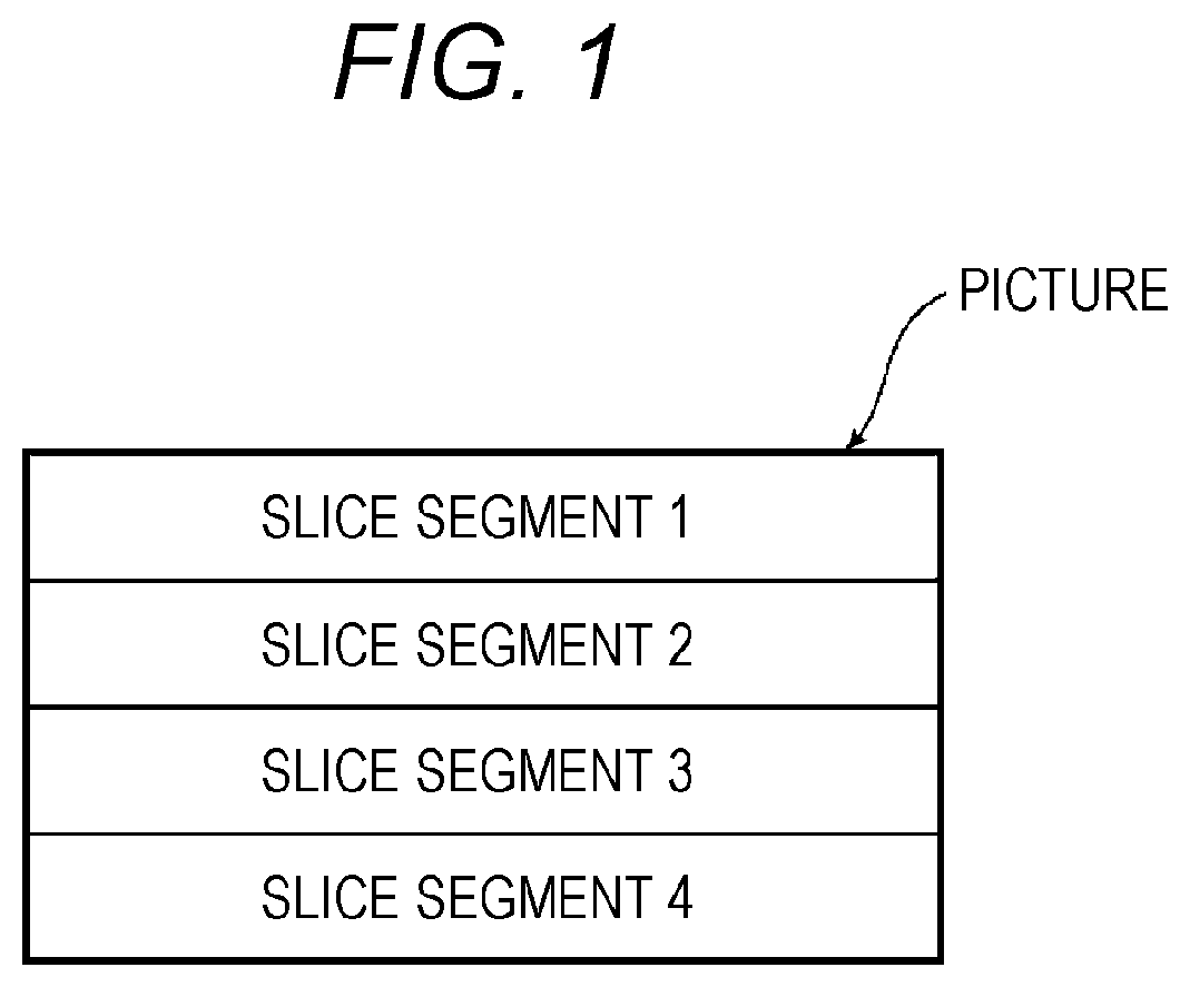
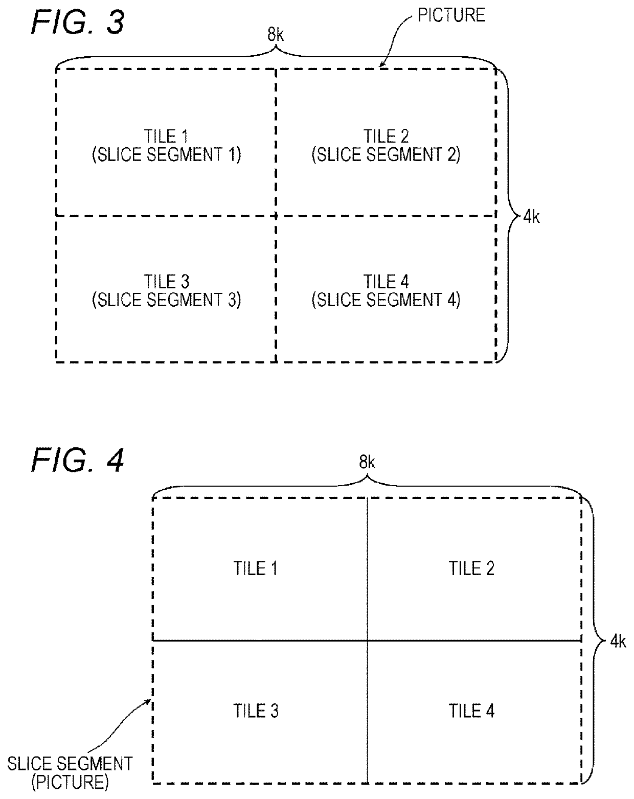
[0124]FIG. 3 is a view illustrating an example where an access unit (picture) according to the present embodiment is divided in division units. The access unit is equally divided into two in horizontal and vertical directions by a function called a tile introduced by H.265, and is divided into four tiles in total. Further, each slice segment and each tile are associated on a one-to-one basis.

[0125]A reason for equally dividing an access unit into two in the horizontal and vertical directions will be described. First, during general decoding, a line memory which stores data of one horizontal line is necessary. However, in the case of an ultra-high resolution such as 8K4K, a horizontal direction size increases, and therefore a line memory size increases. It is...

second exemplary embodiment

[0252]A method for storing data of an NAL size format in an MP4 format-based MPU according to MMT will be described in the second exemplary embodiment. In addition, the method for storing data in an MPU used in MMT will be described as an example below. Such a storage method is applicable to the same MP4 format-based DASH, too.

[0253][Storage Method for MPU]

[0254]According to an MP4 format, a plurality of access units is collectively stored in one MP4 file. Data of each medium is stored in one MP4 file in an MPU used for MMT, and data can include an arbitrary number of access units. The MPU is a unit which can be decoded alone, and therefore access units are stored in the MPU in GOP (Group Of Picture) units.

[0255]FIG. 19 is a view illustrating a configuration of an MPU. An MPU head is ftyp, mmpu and moov which are collectively defined as MPU meta data. Initialization information which is common between each of files, and an MMT hint track are stored in moov.

[0256]Further, information...

third exemplary embodiment

[0576][Outline]

[0577]A content transmitting method and a content data structure in the case where content such as a video, an audio, a caption and data broadcast is transmitted by way of broadcasting will be described in the third exemplary embodiment. That is, the content transmitting method specialized in broadcast stream playback, and the content data structure will be described.

[0578]In addition, an example where an MMT method (referred to simply as MMT below) is used as a multiplexing method will be described in the third exemplary embodiment. However, other multiplexing methods such as DASH and RTP may be used.

[0579]First, a method for storing a data unit (DU) in a payload according to MMT will be described in detail. FIG. 48A, FIG. 48B and FIG. 48C are views for explaining a method for storing a data unit in a payload according to MMT.

[0580]According to MMT, a transmitting device stores part of data configuring an MPU as a data unit in an MMTP payload, adds a header to the da...


PUM


Abstract

A transmitting device includes: a generator that generates an encoded stream by using rate control satisfying a determined definition of a receiving buffer model; and a transmitter that sequentially transmits a transmitting packet, and the receiving buffer model includes a first buffer that converts a packet into a first packet where the packet includes a packet header of a variable length, and the first packet includes a packet header of a fixed length of a decompressed header, a second buffer that converts the first packet into a second packet including a payload of a variable length, a third buffer that converts the second packet into a Network Abstraction Layer (NAL) unit, and a fourth buffer that outputs an access unit generated from a plurality of sequentially accumulated NAL units to a decoder at a timing of a decoding time corresponding to the access unit.

Description

BACKGROUND[0001]1. Technical Field[0002]The present disclosure relates to a transmitting device, a receiving device, a transmitting method and a receiving method.[0003]2. Description of the Related Art[0004]As broadcasting and communication services are sophisticated, introduction of super-high definition moving image content such as 8K (7680×4320 pixels: also referred to as 8K4K) and 4K (3840×2160 pixels: also referred to as 4K2K) has been studied. A receiving device needs to decode and display encoded data of the received ultra-high definition moving image in real time. A processing load of a moving image of a resolution such as 8K in particular is great during decoding, and it is difficult to decode such a moving image in real time by using one decoder. Hence, a method for reducing a processing load of one decoder by parallelizing decoding processing by using a plurality of decoders, and achieving processing in real time has been studied.[0005]Further, encoded data is multiplexed...

Claims


Application Information

Patent Timeline
Patent Type & Authority Patents(United States)
IPC IPC(8): H04N21/236H04N21/24H04N21/434H04N21/4385H04N21/845H04N21/426H04N21/43H04N21/242H04L29/06H04N21/44H04N21/2343H04N21/2389
CPCH04L65/80H04N21/4385H04N21/23605H04N21/234327H04L65/607H04N21/4341H04N21/242H04N21/845H04N21/44004H04N21/4307H04L65/602H04N21/2401H04N21/42615H04N21/2389H04N21/23611H04N21/2343H04N21/43072H04L65/762H04L65/70
Inventor IGUCHI, NORITAKATOMA, TADAMASA
Owner PANASONIC INTELLECTUAL PROPERTY MANAGEMENT CO LTD
Learn More