Plug connector

Active Publication Date: 2020-05-12
CHENG UEI PRECISION IND CO LTD
View PDF5 Cites 4 Cited by
  • Summary
  • Abstract
  • Description
  • Claims
  • Application Information

AI Technical Summary

Benefits of technology

The patent text describes a plug connector with a protecting element that is integrally molded using injection molding technology. The protecting element is fastened between the inner shell and the outer shell using two buckling assemblies, ensuring stability of the plug connector. This fastening method simplifies the manufacturing process and procedures of the plug connector. In summary, the technical effect of this patent text is the integrated molding and fastening of a protecting element in a plug connector, improving product stability.

Problems solved by technology

When the conventional plug connector is inserted into a docking port, because the outer shell is made of the harder material, the outer shell of the conventional plug connector easily scratches or abrades an outer cover of the electronic product to which the conventional plug connector is assembled, consequently, an aesthetic feeling of an appearance of the conventional plug connector is affected.
However, in order to ensure that the protecting element is capable of being connected with and fastened with the plug connector, in the conventional plug connector, the protecting element is fastened to a junction between the connecting element and the outer shell, accordingly an interstice is formed between the protecting element and the outer shell and a manufacturing process of the conventional plug connector is hardly controlled.
Thus the conventional plug connector is incapable of effectively fastening the protecting element thereof, and complicating a manufacturing process and manufacturing procedures thereof.

Method used


Image

  • Plug connector
  • Plug connector
  • Plug connector

Examples


Embodiment Construction

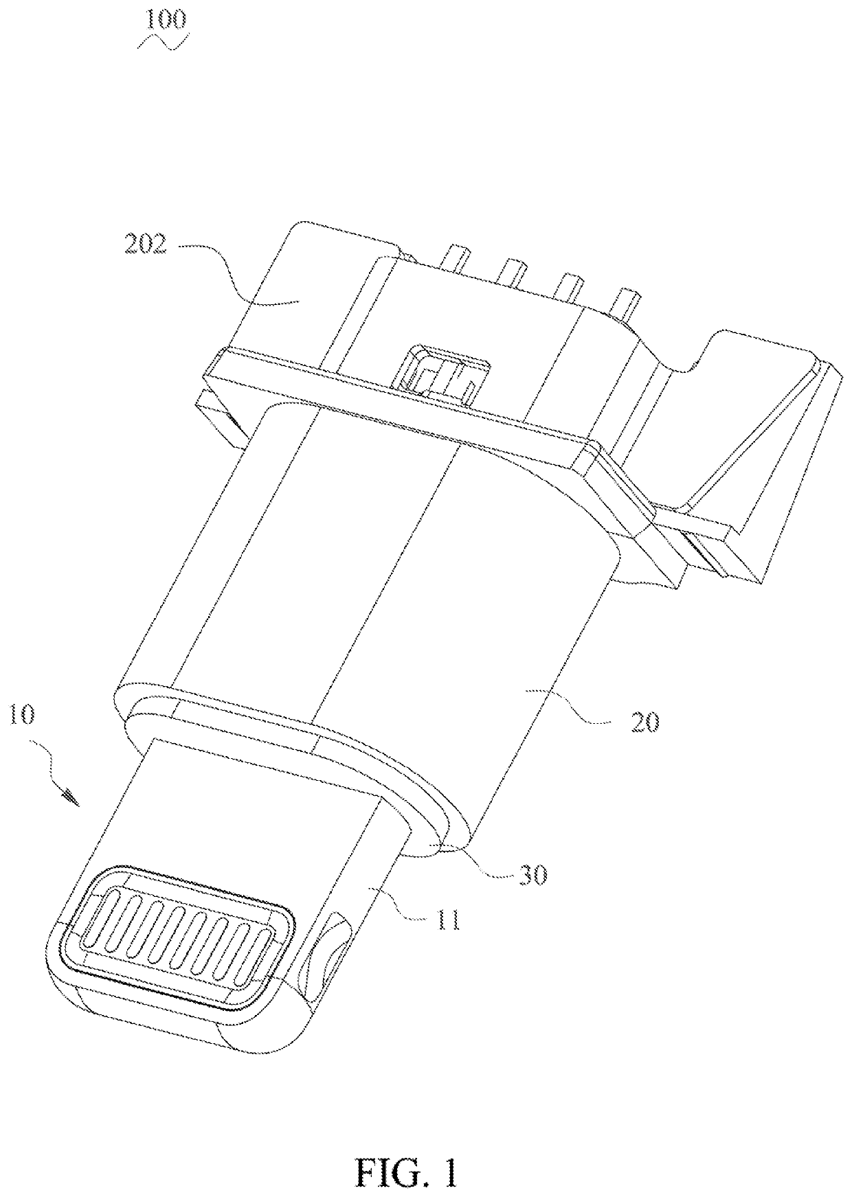
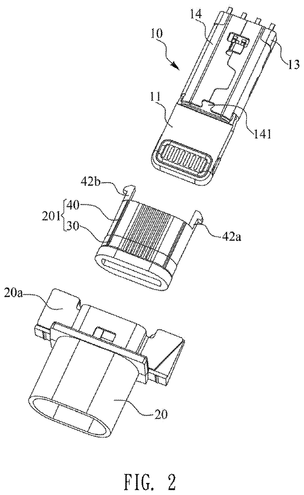
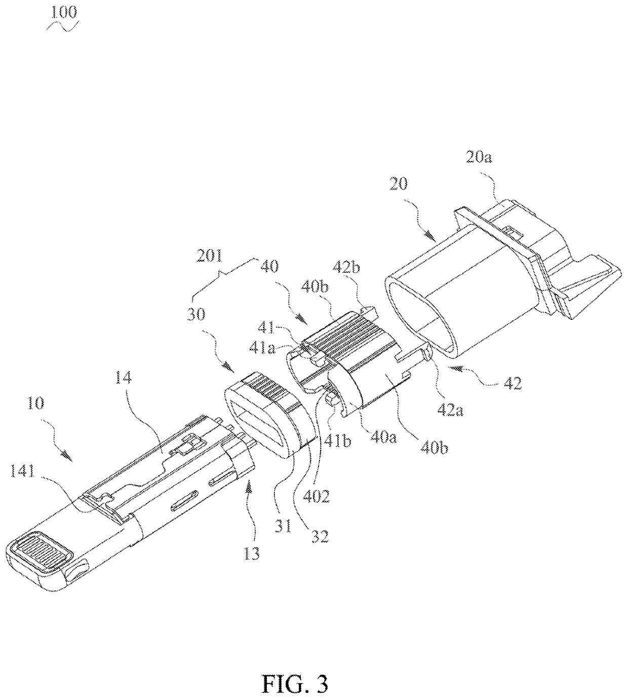
[0016]With reference to FIG. 1, FIG. 2 and FIG. 4, a plug connector 100 in accordance with a preferred embodiment of the present invention is shown. The plug connector 100 includes a main body 10, an integrally molded protecting assembly 201 fastened to a front end of the main body 10, an outer shell 20 which is integrally molded, and a propping element 202. The protecting assembly 201 includes a protecting element 30 and a combination element 40.

[0017]Referring to FIG. 1 to FIG. 4, the main body 10 includes a connecting element 11, a circuit board 12, a soldering element 13 and an inner shell 14. The inner shell 14 has a location function. The connecting element 11 is used for an electrical connection. The circuit board 12 is electrically connected with the connecting element 11. The soldering element 13 is soldered to and fastened to a rear end of the circuit board 12. The inner shell 14 is fastened between the connecting element 11 and the soldering element 13. The inner shell 14...


PUM


Abstract

A plug connector includes a main body, a protecting assembly and an outer shell. The main body includes a connecting element for an electrical connection, a circuit board electrically connected with the connecting element, a soldering element fastened to a rear end of the circuit board, and an inner shell surrounding the circuit board. The protecting assembly is fastened to the main body. The protecting assembly includes a combination element surrounding the inner shell, and a protecting element fastened with the combination element. The outer shell surrounds the inner shell. The protecting element is fastened to a junction among the connecting element, the inner shell and the outer shell. The combination element has a first buckling assembly and a second buckling assembly. The first buckling assembly is buckled with the inner shell. The second buckling assembly is buckled with the outer shell.

Description

CROSS-REFERENCE TO RELATED APPLICATION[0001]The present application is based on, and claims priority from, China Patent Application No. 201920367641.9, filed Mar. 21, 2019, the disclosure of which is hereby incorporated by reference herein in its entirety.BACKGROUND OF THE INVENTION1. Field of the Invention[0002]The present invention generally relates to a connector, and more particularly to a plug connector capable of effectively fastening a protecting element thereof, and simplifying a manufacturing process and manufacturing procedures thereof.2. The Related Art[0003]Generally, a conventional plug connector includes a connecting element, and an outer shell fastened to the connecting element. The outer shell is made of a harder material. When the conventional plug connector is inserted into a docking port, because the outer shell is made of the harder material, the outer shell of the conventional plug connector easily scratches or abrades an outer cover of the electronic product to...

Claims


Application Information

Patent Timeline
IPC IPC(8): H01R12/00H01R24/60H01R4/02H01R13/502H01R13/42H01R13/516H01R13/514
CPCH01R24/60H01R4/02H01R13/516H01R13/502H01R13/42H01R13/514H01R13/506
Inventor SUN, YANG-YANGLEE, MING-WEI
Owner CHENG UEI PRECISION IND CO LTD
Why Eureka
Try Eureka