
Photoluminescent display device and method for manufacturing the same

a technology of photoluminescent display device and manufacturing method, which is applied in the field of display device, can solve the problems of low light energy utilization efficiency, limited viewing angle, and significant light energy loss, and achieve the effect of improving light energy utilization efficiency and increasing the viewing angle of the photoluminescent display devi

Active Publication Date: 2020-04-14
MAVEN OPTRONICS CO LTD
View PDF23 Cites 1 Cited by
  • Summary
  • Abstract
  • Description
  • Claims
  • Application Information

AI Technical Summary

Benefits of technology

[0010]One object according to some embodiments of the present disclosure is to provide a photoluminescent display device and a manufacturing method thereof, so that the light energy utilization efficiency is improved and / or the viewing angle of the photoluminescent display device is increased, while facilitating the manufacturing process of the photoluminescent display device.
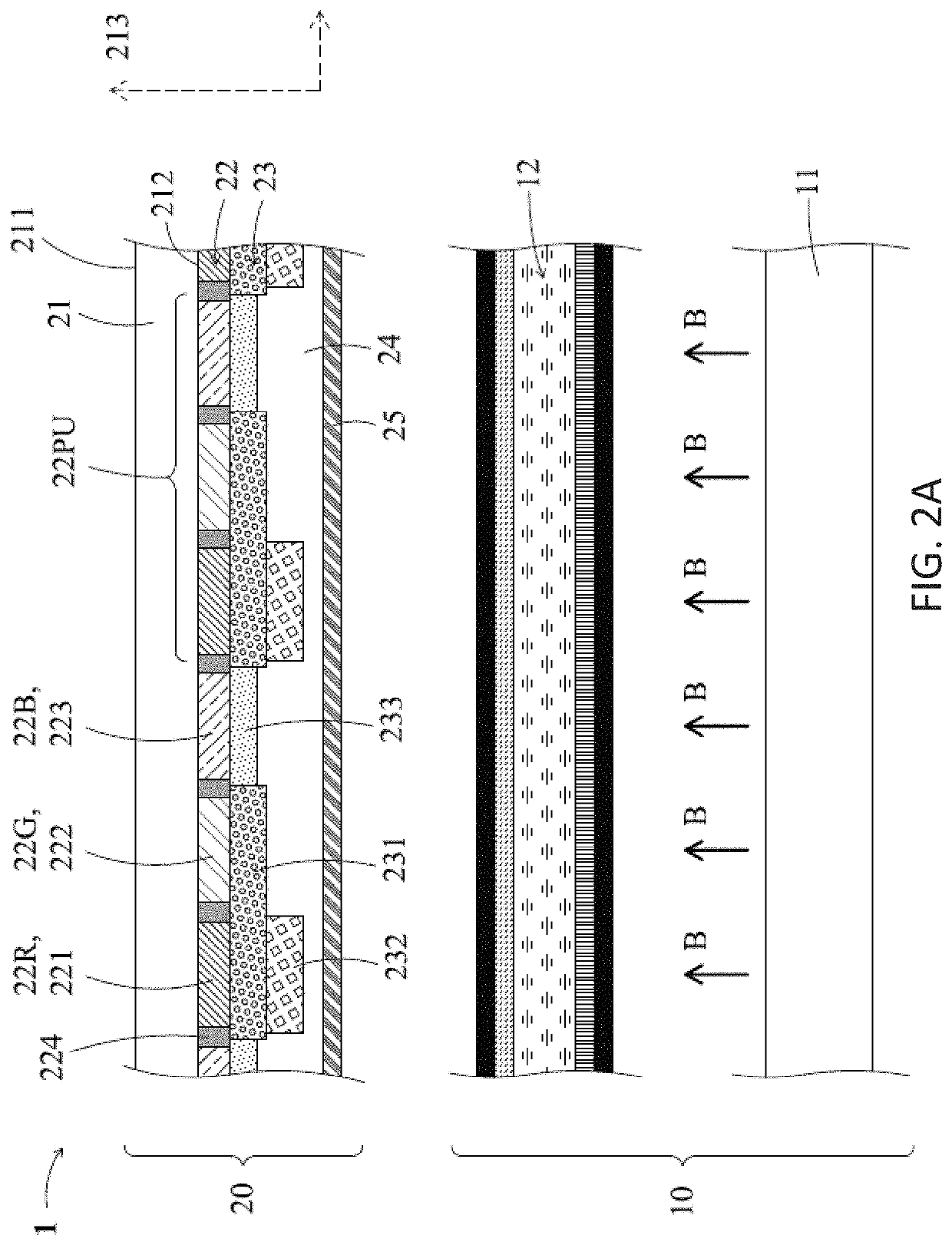
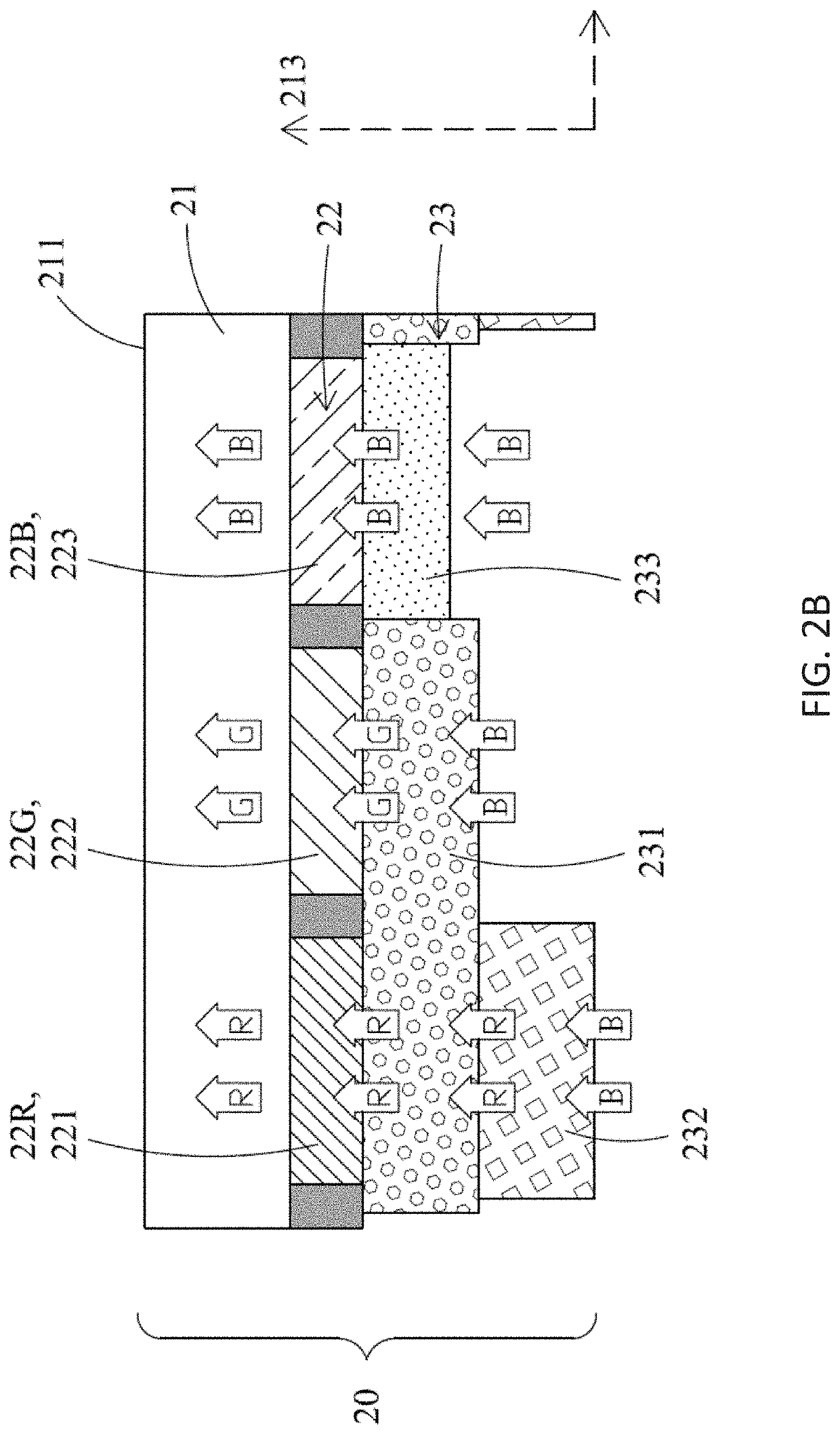
[0013]Therefore, the photoluminescent display device and the method of manufacturing the same according to some embodiments of the present disclosure can provide at least the following benefits. Because the green light-conversion layer of the photoluminescent structure covers at least the red pixel region and the green pixel region of the color filter structure, the green light-conversion layer has a larger pixel size and thus is easier to align green pixels of the photoluminescent light-conversion layer with the underlying color filter pixels during the fabrication process. In addition, the red photoluminescent light-conversion layer is subsequently disposed on the underlying green light-conversion layer to form a stacked photoluminescent structure, rather than a side-by-side photoluminescent structure. This stacked arrangement allows more tolerance for pixel alignment. Therefore, the red light-conversion layer is also easier to be fabricated. Furthermore, since precise alignment between / among light-conversion layers is not needed, the manufacturing yield loss caused by misalignment, is reduced, therefore lowering production cost.
[0014]Further, the photoluminescent display device according to some embodiments of the present disclosure includes the photoluminescent structure with the red light-conversion layer disposed on the green light-conversion layer. This arrangement facilitates the manufacturing process, and also provides improved light energy utilization efficiency. This is because when, for example, a blue light irradiated from the blue light source passes through the red pixel region, it first passes through the red light-conversion layer so that most of the blue light (for example, close to about 100%) is converted into a red light, and then the converted red light continues passing through the green light-conversion layer. Since the red light having a lower energy level will not excite the green photoluminescent material, the red light still keeps the same red spectrum and will not be converted into green light before it reaches the red pixel region of the color filter structure. Since the majority of the light is already in the red spectrum, the light energy will not be absorbed while passing through the red color filter at the location of the red pixel. Light energy utilization efficiency of the photoluminescent display device is therefore improved.
[0015]By contrast, for a comparison LCD device, white light is transmitted to pass through red, green and blue pixel regions of a color filter layer to generate corresponding red, green and blue pixels for color images. A majority of the light energy is filtered out while the white light passes through the color filter, resulting in low light energy utilization efficiency. As for the photoluminescent display device disclosed in some embodiments of the present disclosure, the blue light emitted from the blue backlight source thereof can be converted into the red light, the green light and the un-converted blue light respectively while passing through the pixelated photoluminescent structure and can pass through the corresponding red pixel region, green pixel region and blue pixel region of the color filter structure. Thus almost all of the red light, the green light and the blue light can respectively pass through the red pixel region, the green pixel region and the blue pixel region of the color filter structure without considerable absorption by the color filter structure. As a result, the photoluminescent display device has better overall light energy utilization efficiency, therefore improving the brightness (luminance) of the display device with less power consumption.

Problems solved by technology

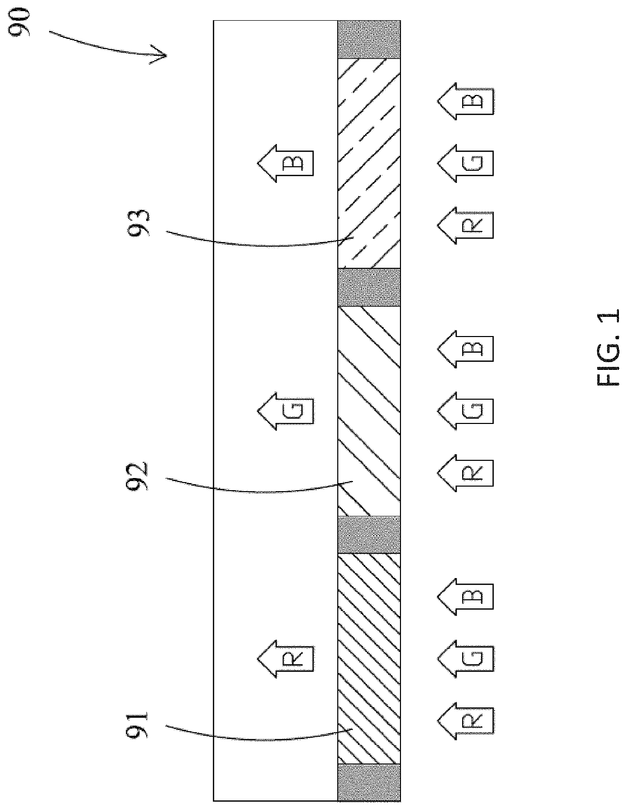
Even though this color filtering mechanism is satisfactory for an LCD device, on the other hand, one major drawback of the color filtering mechanism is that when the white light passes through the pixelated color filter layer 90, a majority (e.g., about two-thirds) of the light spectrum is blocked by the pixelated color filter layer 90, causing a significant light energy loss.
In other words, the light energy utilization efficiency is low.
Another drawback of an LCD device is that the viewing angle is usually limited, which is caused by the working principle of liquid crystal materials.
Even though these technologies can alleviate the drawback of the LCD device with limited viewing angle, however, some accompanying issues arise, such as more complicated fabrication process, higher production costs, lower manufacturing yield, lower light transmission rate, and so forth.
Moreover, although Fujitsu's Wide Viewing Film (WVF) technology has an acceptable production cost with high process compatibility to the existing LCD device manufacturing line, the improvement in increasing viewing angle is relatively small.
It is quite challenging during a manufacturing process to avoid misalignment of photoluminescent light-conversion layers.
For example, a green photoluminescent light-conversion layer may partially cover and then stack up against an adjacent red light-conversion layer due to misalignment during the fabrication process, which results in non-uniform thickness of the pixelated photoluminescent structure and thus poor image quality.
A majority of the light energy is filtered out while the white light passes through the color filter, resulting in low light energy utilization efficiency.

Method used


Image

  • Photoluminescent display device and method for manufacturing the same
  • Photoluminescent display device and method for manufacturing the same
  • Photoluminescent display device and method for manufacturing the same

Examples


Embodiment Construction

Definitions

[0036]The following definitions apply to some of the technical aspects described with respect to some embodiments of the disclosure. These definitions may likewise be expanded upon herein.

[0037]As used herein, the singular terms “a,”“an,” and “the” include plural referents unless the context clearly dictates otherwise. Thus, for example, reference to a layer can include multiple layers unless the context clearly dictates otherwise.

[0038]As used herein, the term “set” refers to a collection of one or more components. Thus, for example, a set of layers can include a single layer or multiple layers. Components of a set also can be referred to as members of the set. Components of a set can be the same or different. In some instances, components of a set can share one or more common characteristics.

[0039]As used herein, the term “adjacent” refers to being near or adjoining. Adjacent components can be spaced apart from one another or can be in actual or direct contact with one ...


PUM

PropertyMeasurementUnit
peak wavelengthaaaaaaaaaa

Abstract

A photoluminescent display device includes a blue light source and a photoluminescent display panel adjoining the blue light source. The photoluminescent display panel includes a transparent substrate, a color filter structure and a photoluminescent structure. The color filter structure includes a red pixel region, a green pixel region and a blue pixel region arranged adjacent to one another on the transparent substrate. The photoluminescent structure, which is disposed on the color filter structure and is facing toward the blue light source, includes a red light-conversion layer and a green light-conversion layer, wherein the red light-conversion layer is disposed on the green light-conversion layer. With this vertically stacked arrangement of the light-conversion layers, the photoluminescent display device can have higher optical energy utilization efficiency and a wider viewing angle, while being easier to be manufactured by relaxing the specification of accurate pixel-level alignment among the light-conversion layers and the color filter structure.

Description

CROSS-REFERENCES TO RELATED APPLICATIONS[0001]This application claims the benefit of and priority to Taiwan Patent Application No. 105116858, and Chinese Patent Application No. 201610373735.8, both filed on May 30, 2016, the disclosures of which are incorporated herein by reference in their entirety.BACKGROUNDTechnical Field[0002]The present disclosure relates to a display device and the manufacturing method thereof, in particular to a photoluminescent display device including a photoluminescent display panel excited by a light source, such as a blue light source.Description of the Related Art[0003]A liquid crystal display (LCD) device is typically composed of two major components: a liquid crystal panel and a backlight unit. The liquid crystal panel generally includes a thin-film transistor (TFT) circuitry, a liquid crystal cell layer, a polarizer, a pixelated color filter layer and so forth. The backlight unit is specified to generate white light, including red, green and blue spe...

Claims


Application Information

Patent Timeline
Patent Type & Authority Patents(United States)
IPC IPC(8): G02F1/1335G02F1/13357G02B5/20
CPCG02F1/133617G02F1/133516G02B5/201G02F1/133514G02F2001/133562G02F1/133562
Inventor CHEN, CHIEH
Owner MAVEN OPTRONICS CO LTD
Learn More