
Optical image capturing module

a technology of optical image and module, applied in the direction of printers, radiation control devices, camera focusing arrangement, etc., can solve the problems of difficult management of assembling and packaging quality of all components, many problems identified but not solved, etc., to achieve the effect of enhancing image quality and reducing the difficulty of light path regulating ability

Active Publication Date: 2020-03-31
ABILITY OPTO ELECTRONICS TECH
View PDF13 Cites 0 Cited by
  • Summary
  • Abstract
  • Description
  • Claims
  • Application Information

AI Technical Summary

Benefits of technology

[0083]The arc length of any surface of a single lens within the height of half the entrance pupil diameter (HEP) particularly affects the surface's ability to correct the aberration and the optical path differences between each of the fields of view at the shared area. The longer the arc length is, the better the ability to correct the aberration will be. However, difficulties may be found in the manufacturing process. Therefore, it is necessary to control the arc length of any surface of a single lens within the height of half the entrance pupil diameter (HEP), especially the ratio (ARE / TP) between the arc length (ARE) of the surface within the height of the half the entrance pupil diameter (HEP) and the thickness (TP) of the lens to which the surface belongs on the optical axis. For instance, ARE11 denotes the arc length of the height of the half the entrance pupil diameter (HEP) of the object side surface of the first lens. TP1 denotes the thickness of the first lens on the optical axis. The ratio between the two is ARE11 / TP1. ARE12 denotes the arc length of the height of the half the entrance pupil diameter (HEP) of the image side surface of the first lens. The ratio between ARE12 and TP1 is ARE12 / TP1. ARE21 denotes the arc length of the height of the half the entrance pupil diameter (HEP) of the object side surface of the second lens. TP2 denotes the thickness of the second lens on the optical axis. The ratio between the two is ARE21 / TP2. ARE22 denotes the arc length of the height of the half the entrance pupil diameter (HEP) of the image side surface of the second lens. The ratio between ARE22 and TP2 is ARE22 / TP2. The ratio between the arc length of the height of the half the entrance pupil diameter (HEP) of any surface of the rest lenses in the optical image capturing module and the thickness (TP) of the lens to which the surface belongs on the optical axis may be deducted on this basis.

Problems solved by technology

With respect to the assembly of video-recording devices at present, many problems have been identified but not solved yet, especially the video-recording devices with multiple lenses.
Due to the use of multiple lenses, there is a dramatic impact on image quality if an optical axis cannot be accurately aimed at a CMOS active pixel sensor for calibration in the process of assembling and manufacturing image quality.
In addition, even though video-recording devices provide an auto-focus function that can be used when the lens is in motion, the assembling and packaging quality of all components would be difficult to manage owing to the complicated composition of the components of the video recording devices.

Method used


Image

  • Optical image capturing module
  • Optical image capturing module
  • Optical image capturing module

Examples


first optical embodiment

The First Optical Embodiment

[0193]As shown in FIG. 18, each of the fixed-focus lens assembly 230 and the auto-focus lens assembly 240 respectively include six lenses 2401 with refractive power, and includes a first lens 2411, a second lens 2421, a third lens 2431, a four lens 2441, a fifth lens 2451, and a sixth lens 2461 sequentially displayed from an object side surface to an image side surface. Each of the fixed-focus lens assembly 230 and the auto-focus lens assembly 240 satisfies the following condition: 0.1≤InTL / HOS≤0.95. Specifically, HOS is the distance on the optical axis from an object side surface of the first lens to the image plane; InTL is the distance on the optical axis from an object side surface of the first lens 2411 to an image side surface of the sixth lens 2461.

[0194]Please refer to FIGS. 20 and 21. FIG. 20 is a schematic view of an optical image capturing module according to the first embodiment in the present invention. FIG. 21 is curve diagrams of spherical ...

second optical embodiment

The Second Optical Embodiment

[0259]As shown in FIG. 19, each of the fixed-focus lens assembly 230 and the auto-focus lens assembly 240 may respectively include seven lenses 2401 with refractive power, and include a first lens 2411, a second lens 2421, a third lens 2431, a four lens 2441, a fifth lens 2451, a sixth lens 2461, and a seventh lens 2471 sequentially displayed from an object side surface to an image side surface. Each of the fixed-focus lens assembly 230 and the auto-focus lens assembly 240 satisfies the following condition: 0.1≤InTL / HOS≤0.95. Specifically, HOS is the distance from an object side surface of the first lens 2411 to the imaging surface on an optical axis, and InTL is the distance from an object side surface of the first lens 2411 to an image side surface of the seventh lens 2471 on an optical axis.

[0260]Please refer to FIG. 22 and FIG. 23. FIG. 22 is a schematic diagram of the optical image capturing module according to the second optical embodiment of the p...

third optical embodiment

The Third Optical Embodiment

[0280]As shown in FIG. 18, each of the fixed-focus lens assembly 230 and the auto-focus lens assembly 240 may respectively include six lenses 2401 with refractive power, and include a first lens 2411, a second lens 2421, a third lens 2431, a four lens 2441, a fifth lens 2451, and a sixth lens 2461 sequentially displayed from an object side surface to an image side surface. Each of the fixed-focus lens assembly 230 and the auto-focus lens assembly 240 satisfies the following condition: 0.1≤InTL / HOS≤0.95. Specifically, HOS is the distance from an object side surface of the first lens 2411 to the imaging surface on an optical axis; InTL is the distance from an object side surface of the first lens 2411 to an image side surface of the sixth lens 2461 on an optical axis.

[0281]Please refer to FIG. 24 and FIG. 25. FIG. 24 is a schematic diagram of the optical image capturing module according to the third optical embodiment of the present invention. FIG. 25 is a ...


PUM

PropertyMeasurementUnit
distanceaaaaaaaaaa
distanceaaaaaaaaaa
field of viewaaaaaaaaaa

Abstract

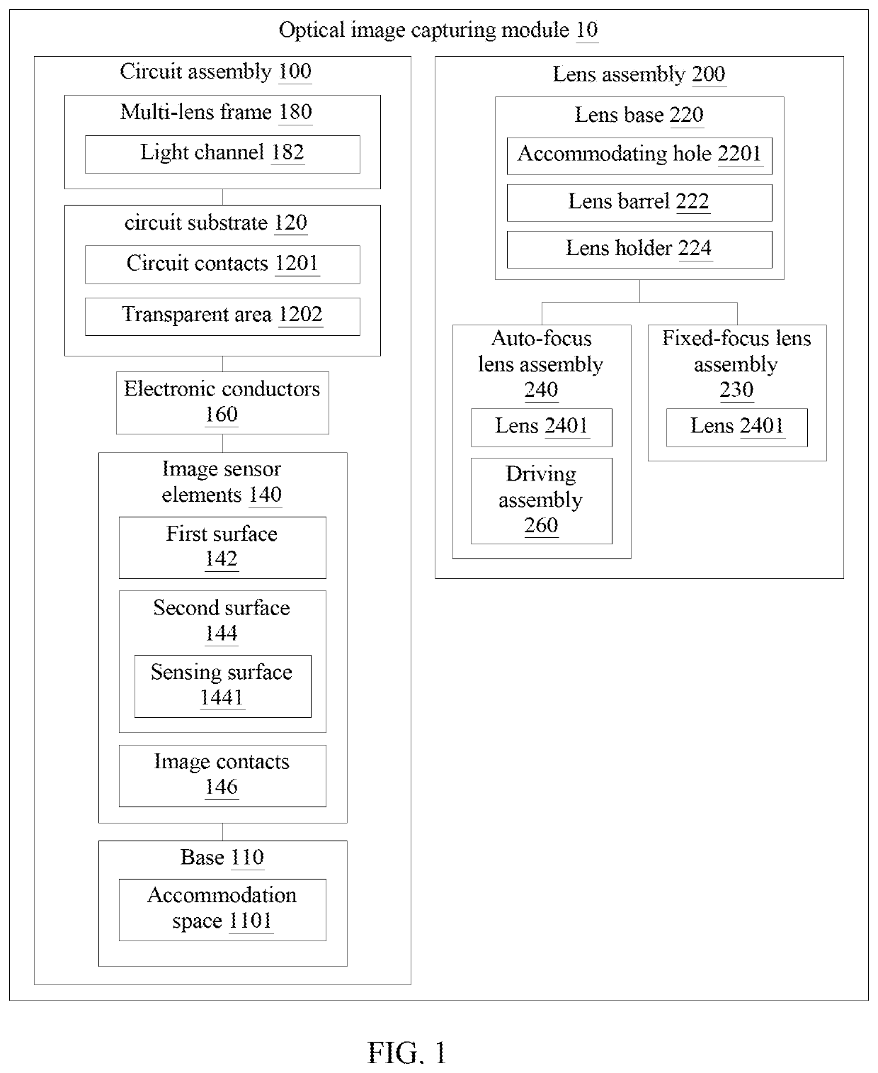
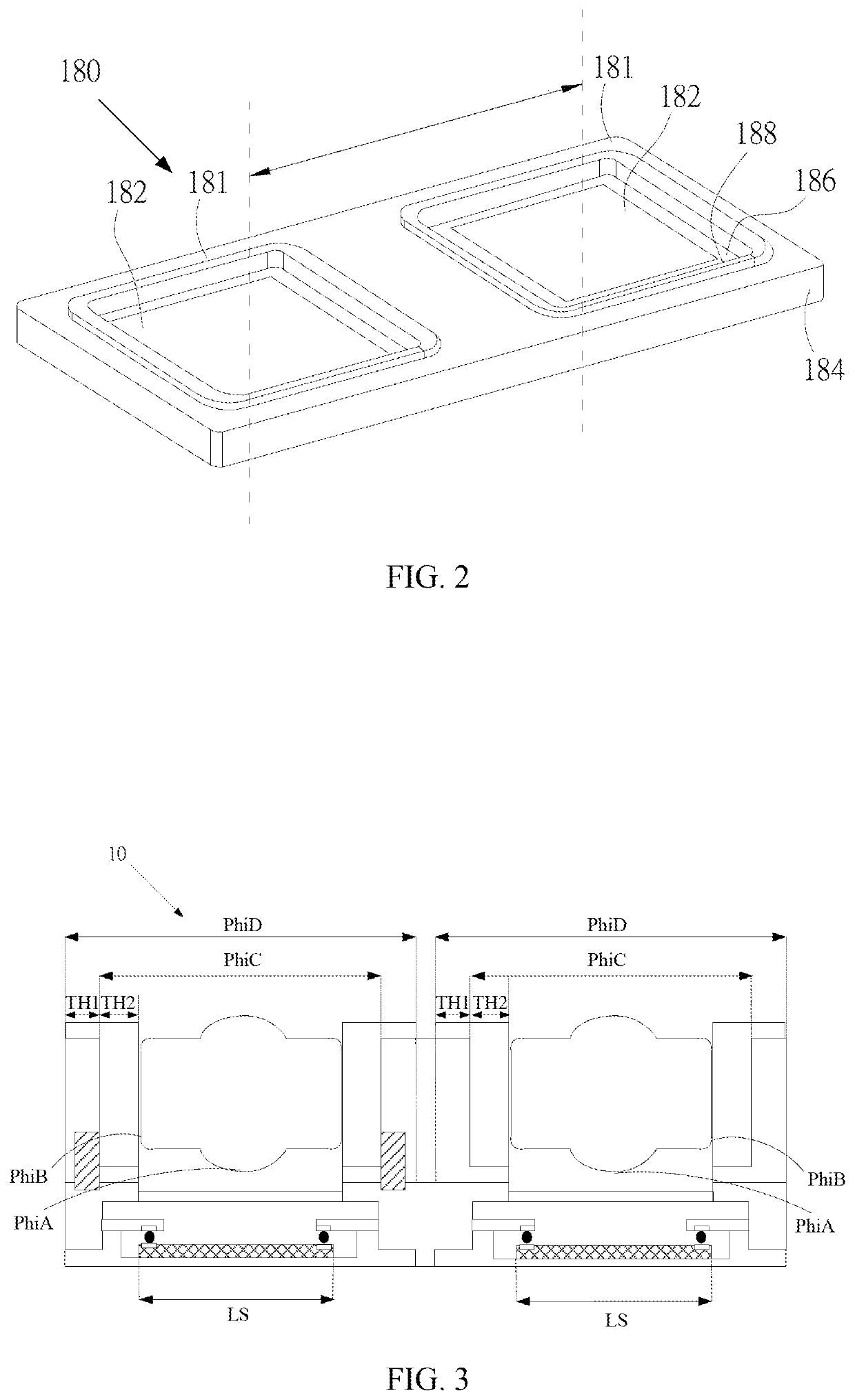
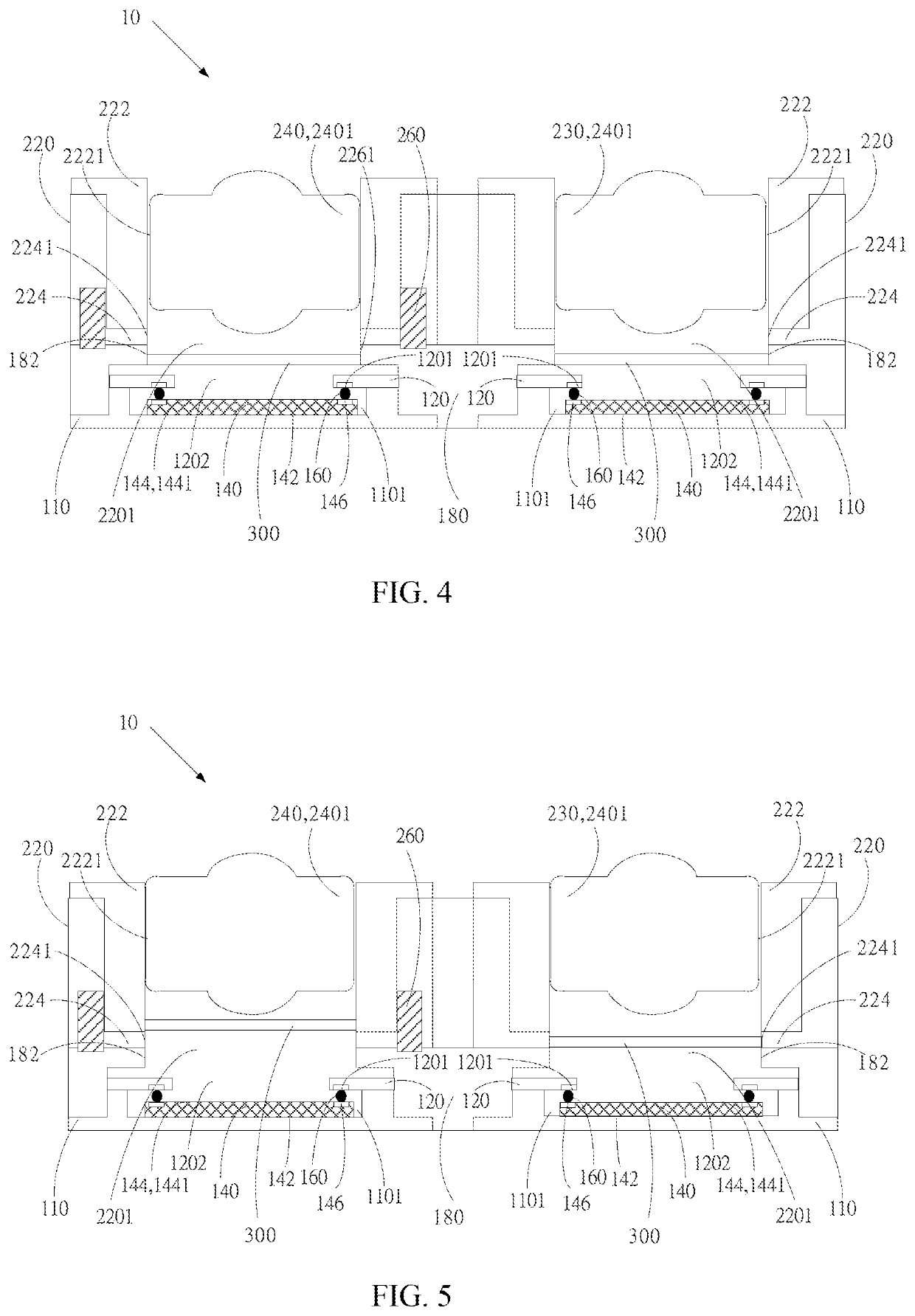
An optical imaging module, including a circuit assembly and a lens assembly, is provided. The circuit assembly includes a base, a circuit substrate, image sensor elements, conductors, and a multi-lens frame. The image sensor elements are disposed in the accommodation space of the base. The conductors are disposed between circuit contacts of the circuit substrate and image contacts of the image sensor elements. The multi-lens frame can be integrally formed and covered on the circuit substrate and the image sensor elements. The lens assembly includes a lens base, a fixed lens assembly, an auto lens assembly, and a drive assembly. The lens base is disposed on the multi-lens frame. Each of the auto lens assembly and the fixed lens assembly has lenses having refractive power. The driving assembly drives the auto lens assembly to move in the direction of the normal line of the sensing surface.

Description

CROSS-REFERENCE TO RELATED APPLICATION[0001]This application claims priority from Taiwan Patent Application No. 107133404, filed on Sep. 21, 2018, in the Taiwan Intellectual Property Office, the content of which is hereby incorporated by reference in its entirety for all purposes.BACKGROUND OF THE INVENTION1. Field of the Invention[0002]The present invention relates to an optical image capturing module, more particularly to an optical image capturing module which provides a fixed-focus lens assembly and an auto-focus lens assembly, and has a multi-lens frame manufactured integrally; and the present invention further provides an imaging system using the optical capturing module, and a manufacturing method of the optical image capturing module.2. Description of the Related Art[0003]With respect to the assembly of video-recording devices at present, many problems have been identified but not solved yet, especially the video-recording devices with multiple lenses. Due to the use of mult...

Claims


Application Information

Patent Timeline
Patent Type & Authority Patents(United States)
IPC IPC(8): H04N5/225H04N5/232H01L27/146G03B13/36G02B7/00G02B7/02G02B7/10G03B17/12
CPCH04N5/23212G03B13/36H04N5/2254H01L27/14689H01L27/14627G02B7/021G02B7/10G02B7/006G02B13/0045G02B13/18G03B17/12H04N23/54H04N23/45H04N23/50H04N23/55H01L27/14623H01L27/14625H01L27/14618G03B37/04G03B3/10G03B2205/0069G06F1/1686H04N23/57H04N23/67
Inventor CHANG, YEONG-MINGLAI, CHIEN-HSUNLIU, YAO-WEI
Owner ABILITY OPTO ELECTRONICS TECH
Learn More