
Lens for improved color mixing and beam control of an LED light source

a technology of led light source and color mixing, which is applied in the field of total internal reflection (tir) lenses, can solve the problems of reducing the desired color mixing effect, and achieve the effect of improving the color mixing of led outpu

Active Publication Date: 2020-03-17
LUTRON TECH CO LLC
View PDF17 Cites 5 Cited by
  • Summary
  • Abstract
  • Description
  • Claims
  • Application Information

AI Technical Summary

Benefits of technology

[0021]The problems outlined above are in large part solved by an improved lens having a straight entry at the inner radial region to improve color mixing of LED output near a central axis and at the detriment of collimation from that inner radial region. The improved lens also has a straight sidewall entry at the outer radial region to improve color mixing of LED output farther from the central axis even though such LED output is collimated. The straight sidewall entry is, however, configured with a surface that diffuses or scatters the light from the LED as it impinges upon a CPC reflective output surface and then to a concave spherical exit bounded by the CPC reflective outer surface. By configuring the non-collimated light exiting the inner radial region and the collimated, yet diffusion treated, light exiting the outer radial region, the outer radially emitted light surrounds the inner radially emitted light to make the projected light appear in the near and far field to be better color mixed across a broader angular range of the LED output. The lens, used as a secondary optical element, therefore achieves an improved methodology for transferring color mixed light from one or more LEDs.
[0028]According to all embodiments, the lens hereof purposely avoids using any housing reflector, but is implemented in a PAR form factor that provides uniform color throughout the standard 0°, 25°, and upwards to 40° beam angles. The lens preferably has a pipe from the entry portion to the exit portion of no more than 1.4 inches, with the spherical concave exit surface extending to the TIR reflector surfaces being no more than 2.5 inches. The bottom diameter of the lens at the base plane is no more than 1 inch. Accordingly, the present lens is compact; thus, illustrating one benefit of using a CPC dimension rather than a standard parabolic dimension. The relatively small form factor that utilizes a compact design implemented through a CPC configuration achieves not only superior color mixing with improved, if not superior, brightness control, but does so using the unique lens configuration on both the entry and exit surfaces, and further being able to adjust the drive current supplied to the LED loads to accommodate any changes in wavelength-dependent refraction.
[0031]According to an alternative embodiment, a lens within an illumination device is provided that can achieve lessened glare output while maintaining adequate color mixing and beam control through the secondary optical element, or lens. The alternative lens configuration is one that implements a tapered cylindrical opening, rather than a cylindrical opening having a straight sidewall. The tapered sidewall of the lens inner radial region is proximate the light entry region, and can include a diffusion treated surface upon a first plurality of lunes to maintain sufficient beam control. The diffusion treated first plurality of lunes also provides appropriate color mixing.
[0032]Importantly, the concave spherical surface of the light exit region does not have any diffusion treatment on that surface. By avoiding any diffusion treatment, or any manufactured diffusion surface, the concave spherical surface of the light exit region is left clear and relatively smooth as a lens is taken from a smooth injection mold device surface. An exit surface that is not diffusion treated, or diffusion manufactured through texturing via etching, sandblasting, or by configuring a micro-lens array on the surface, the exit surface therefore beneficially reduces any glare output from the illumination device and through the lens. Eliminating any diffusion treatment, manufactured diffusion, or texturing on the entire concave spherical surface of the light exit region, various forms of direct and indirect glare are minimized.
[0036]According to yet a further embodiment of the alternative embodiment, the tapered sidewall surface includes a plurality of planar lunes extending radially inward toward the central axis from the opening to the upper plane, with a manufactured or diffusion treated surface on each of the plurality of lunes. The plurality of planar lunes along the tapered sidewall surface are referred to as a first plurality of lunes. A second plurality of lunes exists on the TIR outer surface and are used to internally reflect any light entering the lens back out to the light exit region, and specifically the concave spherical surface of the lens. The second plurality of lunes assist in color mixing while collimating the light exiting the light exit region. The second plurality of lunes extends from the tapered cylindrical opening to the concave spherical surface at the light exit region, whereby the second plurality of lunes outnumber the first plurality of lunes by a ratio of between 1.5:1 to 2.5:1.

Problems solved by technology

If more than 20 lunes are used, for a given lens dimension, more collimation can occur for radially extending LED light output, which is deleterious to the desired color mixing in the inner radial region of the lens.

Method used


Image

  • Lens for improved color mixing and beam control of an LED light source
  • Lens for improved color mixing and beam control of an LED light source
  • Lens for improved color mixing and beam control of an LED light source

Examples


Embodiment Construction

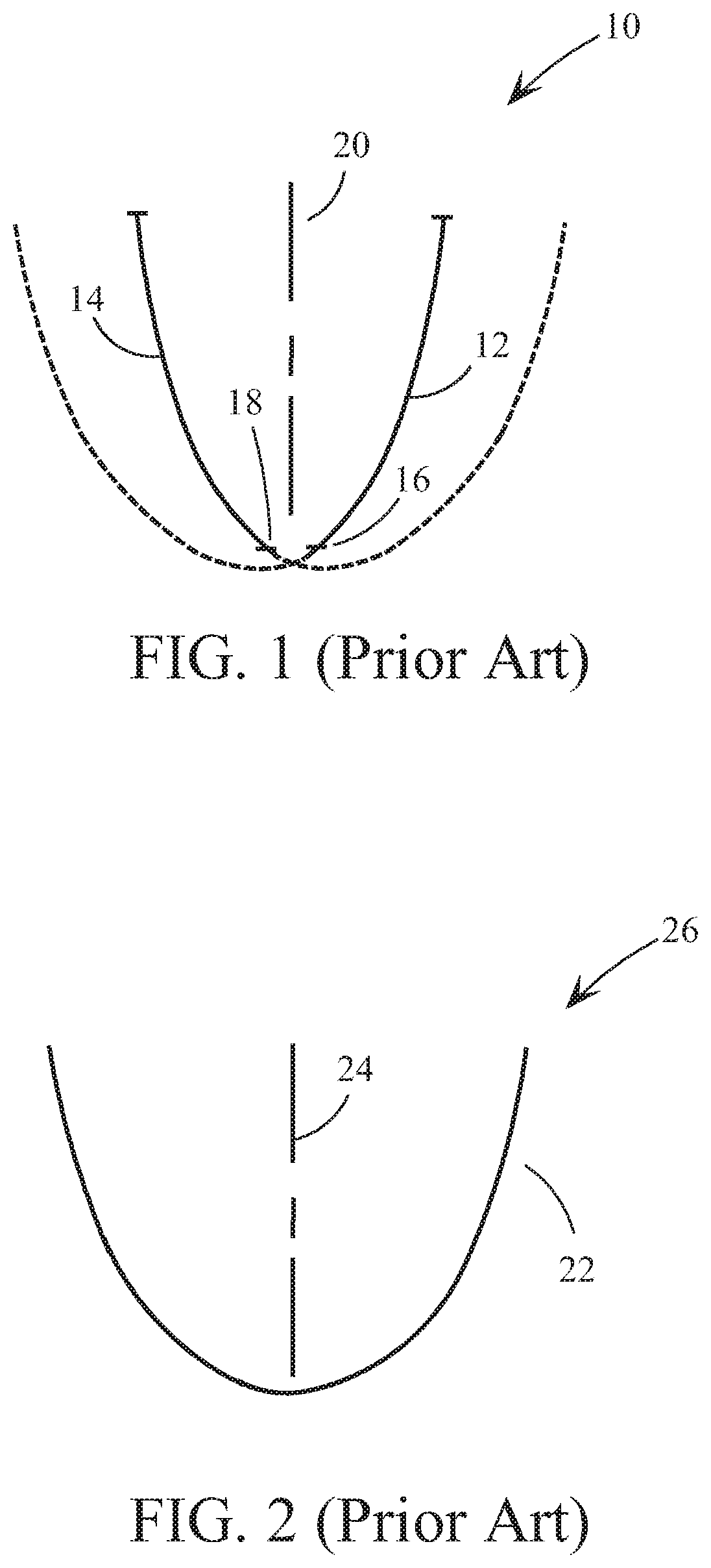
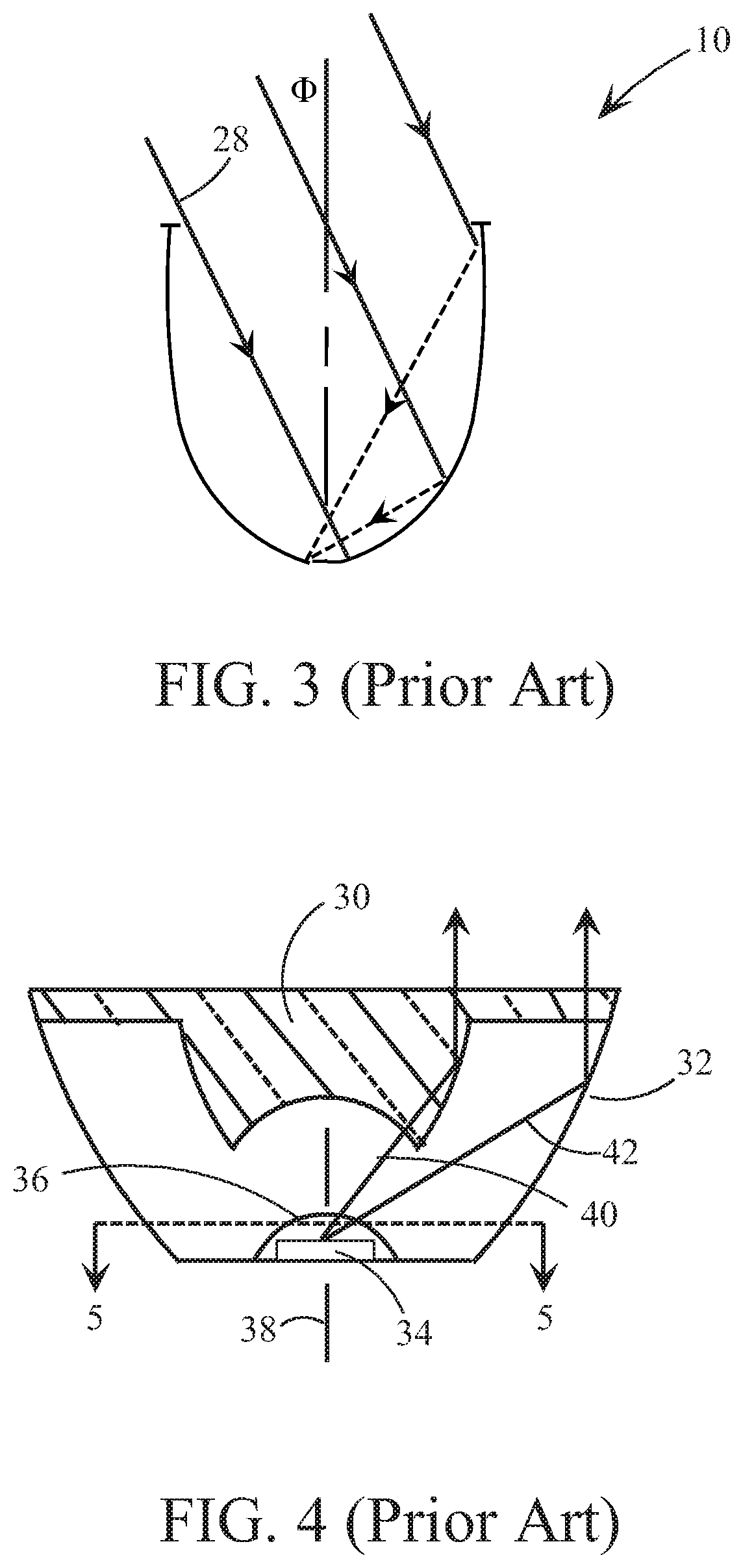
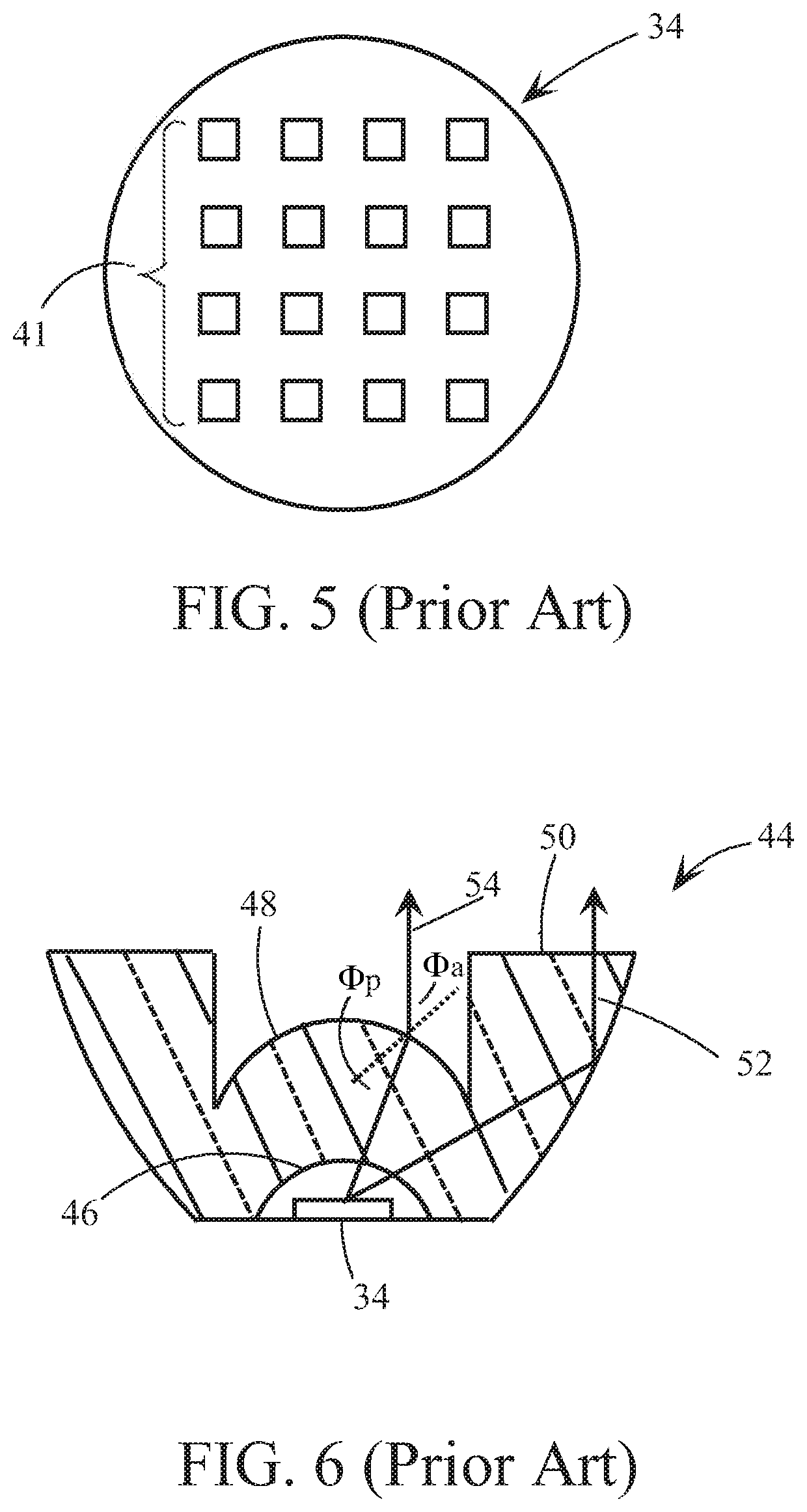
[0053]FIG. 8A illustrates lens 80 filled with material 82, e.g., an injection molded light transparent material. Material82 is bound between light entry region 84, light exit region 86, and TIR outer surface 88, which is shaped as a CPC. TIR outer surface 88 has a smaller exit region then a parabolic TIR, shown in dashed line 90. Moreover, exit region 86 comprises concave spherical surface 94, instead of most conventional parabolic lenses having a flat surface, shown in dashed line 96. Thus, FIG. 8A illustrates a comparison between a conventional parabolic lens 91 and the present lens 80. Present lens 80 is not only shaped as a CPC, but also is more compact in its configuration, being less than 2.5 inches in diameter for exit region 86, 1 inch in diameter for entry region 84, and no more than 1.4 inches in height from the entry region to the exit region. The entry region is defined as a planar base on which the LEDs 100 reside. The overall maximum height of the compact PAR dimension...


PUM

PropertyMeasurementUnit
radial angleaaaaaaaaaa
angleaaaaaaaaaa
beam anglesaaaaaaaaaa

Abstract

A multi-color LED illumination device and specifically a lens comprising a cylindrical opening extending into the lens from a light entry region at which one or more LEDs are configured. A concave spherical surface extends across the entirety of the light exit region of the lens, and a TIR outer surface shaped as a CPC extends between the light entry region and the light exit region. There are various diffusion surfaces placed on the sidewall surface of the cylindrical opening, as well as its upper planar surface and, depending on whether glare control is not needed, the exit surface of the lens. Lunes can also be configured on the sidewall surfaces of the cylindrical opening and if lessening glare is needed, also on the TIR outer reflective surface. The combination of lunes, diffusion elements, and the overall configuration of the lens provides improved color mixing and output brightness according to one embodiment. According to another embodiment, diffusion elements are manufactured and possibly increased on only select surfaces but not on the light exit region in order to lessen glare. Three light interactions in a first portion of light and two interactions in a second portion of light can improve color mixing and beam control. Those interactions includes two refractions either with an intermediate reflection or not, all of which are necessary to achieve the improved performance of the multi-color LED illumination device and lens hereof.

Description

RELATED APPLICATIONS[0001]This application is a continuation-in-part of application Ser. No. 15 / 000,469, which was filed Jan. 19, 2016, which is incorporated in its entirety herein by reference.BACKGROUND OF THE INVENTION1. Field of the Invention[0002]This invention relates to a light emitting diode (LED) illumination device, and more particularly to a total internal reflection (TIR) lens with an outer compound parabolic concentrator (CPC) surface to more efficiently mix LED output in a relatively small parabolic aluminum reflector (PAR) configuration and, according to another embodiment, can lessen glare output while maintaining sufficient color mixing and beam control.2. Description of the Relevant Art[0003]In the field of optics, and specifically non-imaging optics, there are generally two types of optic devices that transfer light radiation between a source and a target. A first type of optic device is oftentimes referred to as an illuminator; the second type of optic device is ...

Claims


Application Information

Patent Timeline
Patent Type & Authority Patents(United States)
IPC IPC(8): F21V5/04F21K9/68F21K9/66F21K9/69G02B3/00G02B19/00F21V7/00F21V5/00F21V7/06F21Y115/10
CPCF21K9/66G02B19/0028F21K9/69G02B3/00G02B19/0061F21V5/04F21K9/68F21V7/06F21Y2115/10F21V7/0091F21V5/007
Inventor DONG, FANGXU
Owner LUTRON TECH CO LLC
Learn More