
Vertical take-off and landing aircraft

a vertical take-off and landing technology, applied in the direction of vertical landing/take-off aircraft, energy-saving board measures, canard-type aircraft, etc., can solve the problems of introducing a failure path, limited range, high construction and maintenance costs, etc., to reduce noise, increase efficiency, and significant range

Active Publication Date: 2020-03-03
BCG DIGITAL VENTURES GMBH
View PDF19 Cites 15 Cited by
  • Summary
  • Abstract
  • Description
  • Claims
  • Application Information

AI Technical Summary

Benefits of technology

[0006]The present invention is directed to a VTOL aircraft with significant range, decreased noise, and increased efficiency.

Problems solved by technology

The first category employs a joined lift-plus-cruise propulsion system, which suffers from limited range due to inefficiencies in producing powered lift.
This concept, however, relies on a complex tilting mechanism that is heavy, introduces a failure path, and is costly to build and maintain.
Existing VTOL aircraft, such as the VTOL aircraft described by Niedzballa, suffers from a number of limitations.
For example, significant vibration during transition flight is generated when a single attachment point is used between each rotor boom and the fuselage.
In addition, constraining the rotor blades to the dimensions of the pylon imposes limitations on the number of rotors that may be employed in a given aircraft.
Finally, in addition to added weight, cost, and complexity, stowing rotors within the rotor booms behind a closeable door does not appreciably reduce drag, can increase noise dramatically, and decreases rotor efficiency.

Method used


Image

  • Vertical take-off and landing aircraft
  • Vertical take-off and landing aircraft
  • Vertical take-off and landing aircraft

Examples


Embodiment Construction

[0044]Preferred embodiments of the present invention may be described hereinbelow with reference to the accompanying drawings. In the following description, well-known functions or constructions are not described in detail because they may obscure the invention in unnecessary detail. For this disclosure, the following terms and definitions shall apply.

[0045]As used herein, the words “about” and “approximately,” when used to modify or describe a value (or range of values), mean reasonably close to that value or range of values. Thus, the embodiments described herein are not limited to only the recited values and ranges of values, but rather should include reasonably workable deviations.

[0046]As utilized herein, “and / or” means any one or more of the items in the list joined by “and / or”. As an example, “x and / or y” means any element of the three-element set {(x), (y), (x, y)}. In other words, “x and / or y” means “one or both of x and y”. As another example, “x, y, and / or z” means any el...


PUM


Abstract

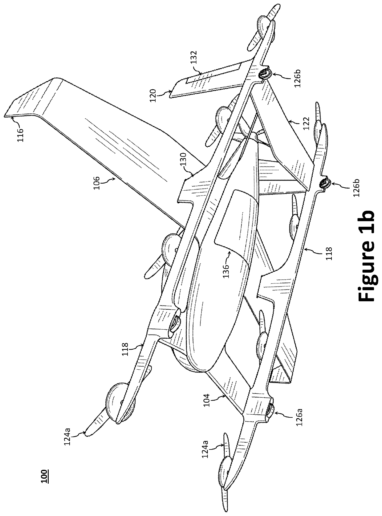
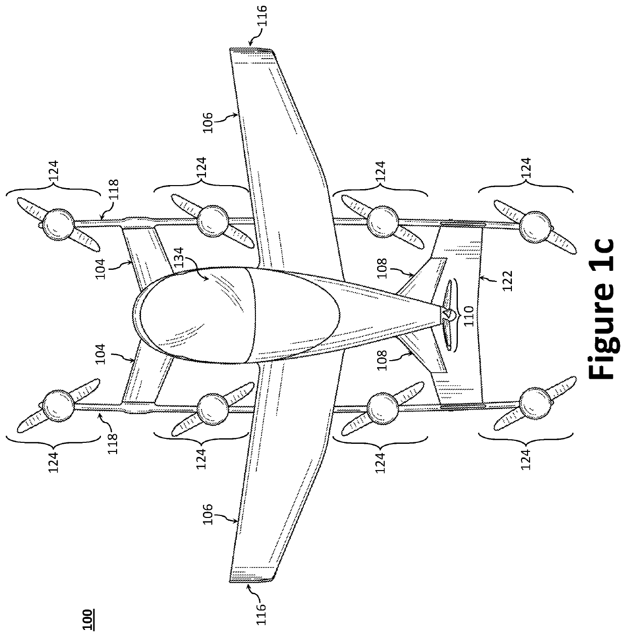
Disclosed herein is a vertical take-off and landing (VTOL) aircraft having three lifting surfaces and separate lift and cruise systems. The VTOL aircraft may include a fuselage having a roll axis, a thrust rotor to produce a propulsion thrust, first and second rotor booms, first and second canard surfaces, first and second wing surfaces, first and second tail surfaces, and a plurality of lift rotors to produce a lifting thrust force. The plurality of lift rotors includes a first plurality of lift rotors positioned on the first rotor boom and a second plurality of lift rotors positioned on the second rotor boom. The first and second rotor booms may be substantially parallel to the roll axis of the fuselage, where the fuselage is positioned between the first and second rotor booms. Each of the first and second rotor booms may be secured to the aircraft at three locations.

Description

TECHNICAL FIELD[0001]The present invention relates to a vertical take-off and landing (VTOL) aircraft, more specifically, to a VTOL aircraft with significant range, even more specifically to a VTOL aircraft having three lifting surfaces and separate lift and propulsion systems.BACKGROUND[0002]VTOL aircraft typically fall into one of three different propulsion system categories. The first category employs a joined lift-plus-cruise propulsion system, which suffers from limited range due to inefficiencies in producing powered lift. A second category employs a tilting mechanism to turn (redirect) the force produced by the rotors from lift to cruise thrust once at a predetermined altitude. This concept, however, relies on a complex tilting mechanism that is heavy, introduces a failure path, and is costly to build and maintain.[0003]A third category employs a series of rotors, each of which is individually dedicated to either lift or cruise thrust, where the lift rotors are only active du...

Claims


Application Information

Patent Timeline
Patent Type & Authority Patents(United States)
IPC IPC(8): B64C27/26B64C39/08B64C39/12B64D27/24B64C29/00B64C27/30
CPCB64C29/0025B64C27/30B64D27/24B64C39/12B64C27/26B64C39/08Y02T50/50Y02T50/40Y02T50/60
Inventor PARKS, ROBERT W.GIANNINI, FRANCESCOSIEGEL, DIANALIENHARD, JAN D.
Owner BCG DIGITAL VENTURES GMBH
Learn More