
Centrifugal separating assembly for positioning a layer of a fluid biological product at a selected location

a technology of centrifugal separation and fluid biological product, which is applied in the direction of centrifuges, laboratory glassware, instruments, etc., can solve the problems of reducing the optimization of a desired concentrate, and affecting the efficiency of centrifugal separation

Active Publication Date: 2020-02-18
HAMANDI ZIAD +1
View PDF3 Cites 4 Cited by
  • Summary
  • Abstract
  • Description
  • Claims
  • Application Information

AI Technical Summary

Benefits of technology

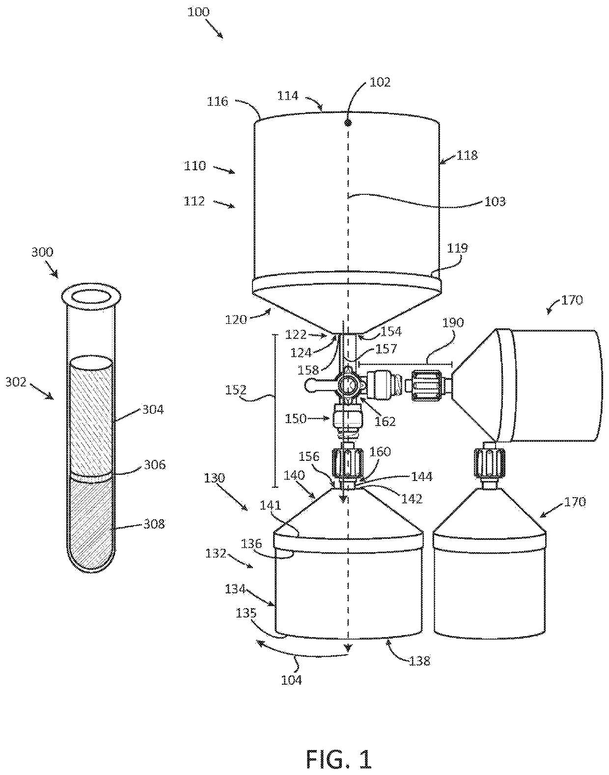
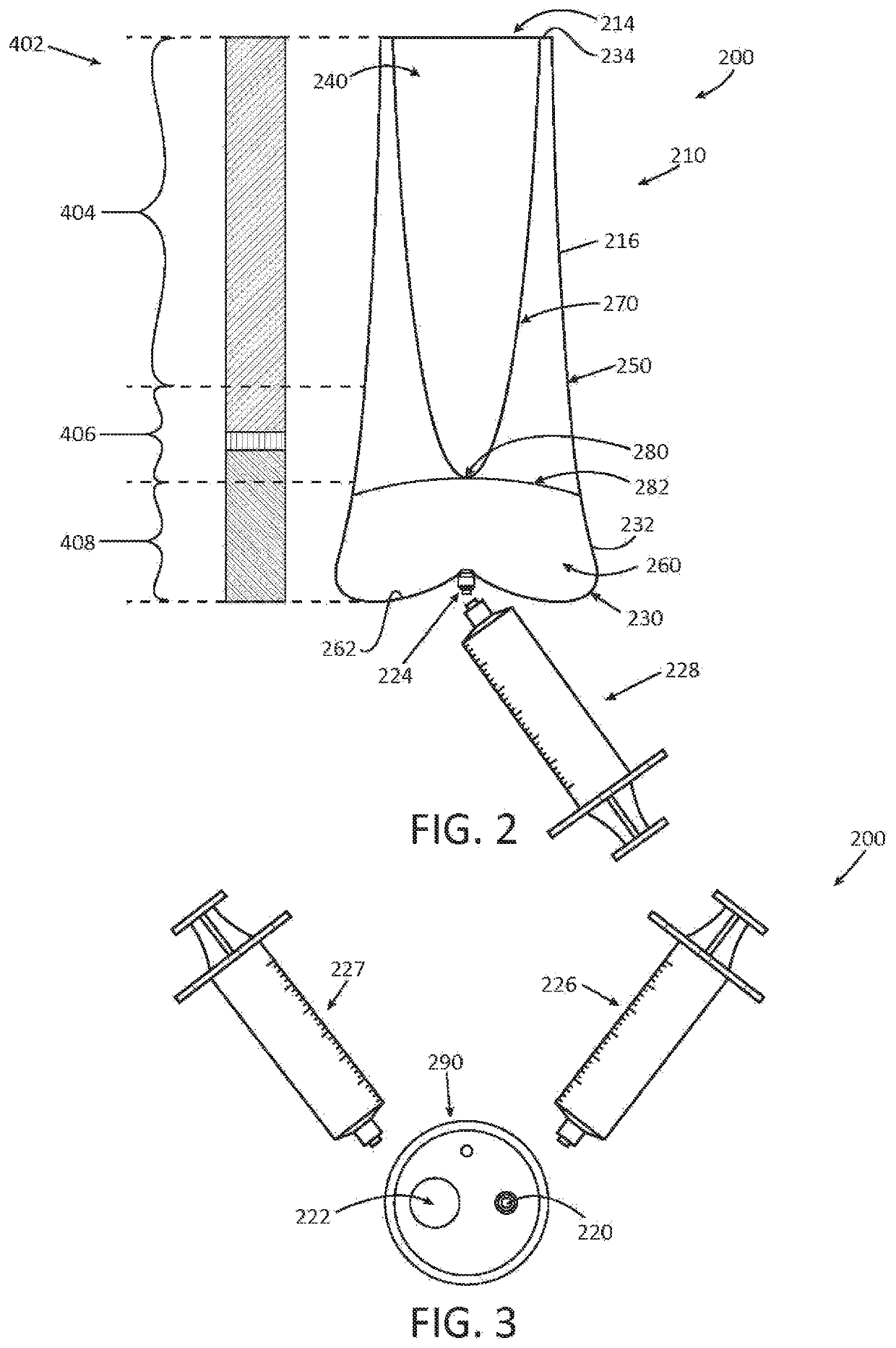
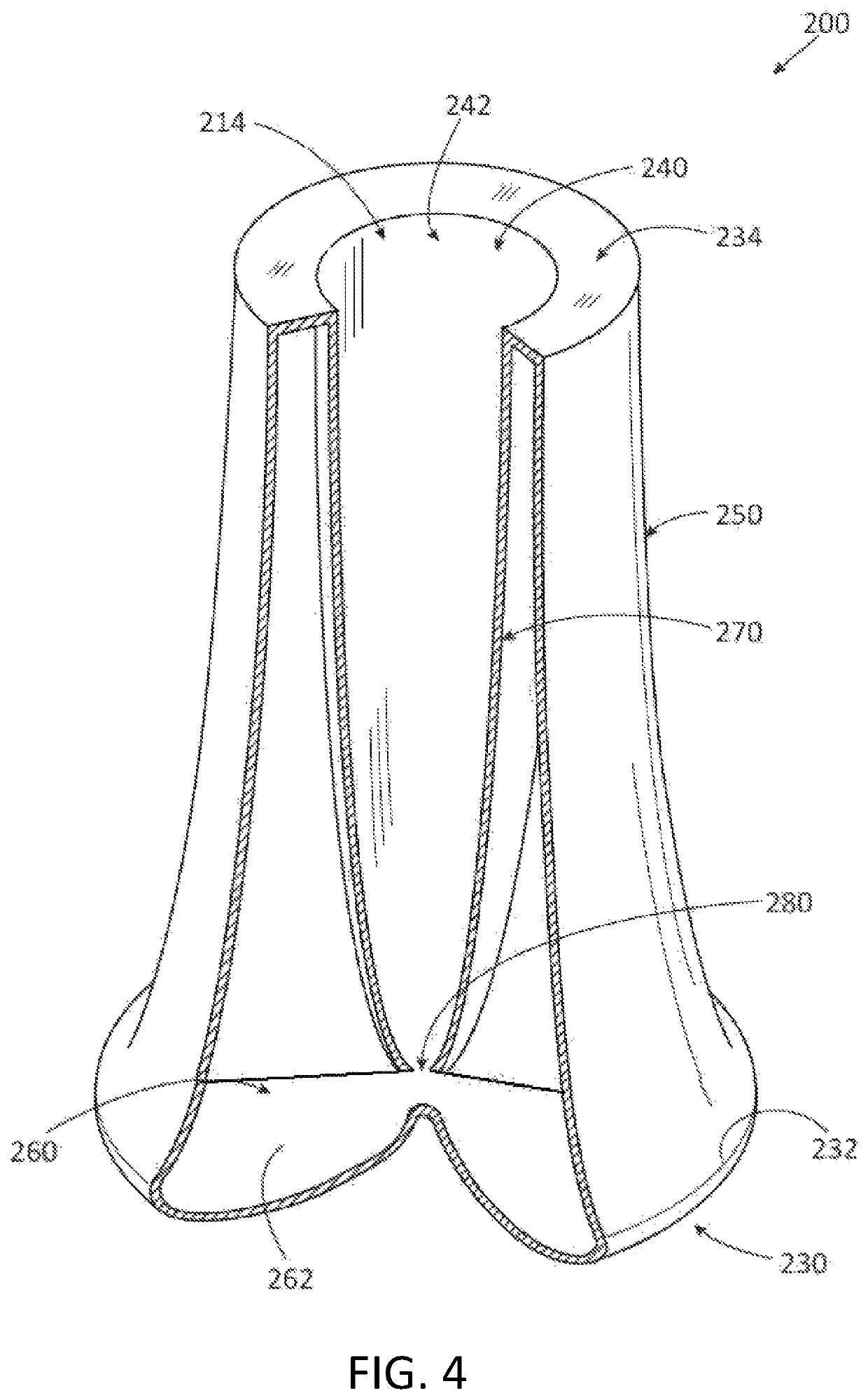
The present invention provides a centrifugal separating assembly for separating a fluid biological product into discrete components. The assembly includes a first container and a second container, each with a different cavity for holding different components of the fluid biological product. The first container has a circular upper wall, a cylindrical wall, and a concave shaped bottom wall, while the second container has a convex shaped upper wall and a cylindrical wall. The two containers are connected by a tubular conduit with a linear length. The assembly also includes a cap that can be fitted to the upper rim of the first container to form a seal and an entry port and an exit port for introducing and removing the fluid biological product. The assembly can be made of polycarbonate. The technical effects of the invention include improved separation of fluid biological products, increased efficiency of the assembly, and better control over the volume of each component.

Problems solved by technology

However, many prior art devices are configured such that adjusting the ratio of red blood cells in the buffy coat requires several steps and is cumbersome to achieve.
Also, many prior art devices are configured such that particulate residue builds on the sidewalls over time, reducing optimization of a desired concentrate.
Unfortunately, known methods of centrifugation result in a buffy coat layer that is minimal in comparison to the overall volume of a blood sample, thus making the buffy coat difficult to analyze.
In addition, many prior art methods of centrifugation do not allow a physician to selectively choose the concentration of white blood cells present in the buffy coat layer.
In the same vein, such methods of centrifugation do not provide the physician with the ability to selectively alter the presence of stem cells obtained from a bone marrow sample for reintroduction at a patient's injury site.
Furthermore, many prior art devices include numerous moving parts that are difficult to operate and which are prone to user error.

Method used


Image

  • Centrifugal separating assembly for positioning a layer of a fluid biological product at a selected location
  • Centrifugal separating assembly for positioning a layer of a fluid biological product at a selected location
  • Centrifugal separating assembly for positioning a layer of a fluid biological product at a selected location

Examples


Embodiment Construction

[0083]While the specification concludes with claims defining the features of the invention that are regarded as novel, it is believed that the invention will be better understood from a consideration of the following description in conjunction with the drawing figures, in which like reference numerals are carried forward. It is to be understood that the disclosed embodiments are merely exemplary of the invention, which can be embodied in various forms.

[0084]The present invention provides a novel and efficient method and device for separating particulates from a solution. Embodiments of the invention provide a centrifugal separating assembly including a first container and a second container coupled via a tubular conduit, the assembly adapted to separate particulates of different densities (or weights) into discrete layers by centrifugation. In addition, embodiments of the invention provide an integral unitary container having a first cavity and a second cavity coupled via a common p...


PUM

PropertyMeasurementUnit
diameteraaaaaaaaaa
diameteraaaaaaaaaa
volumeaaaaaaaaaa

Abstract

A centrifugal separating assembly for separating a fluid biological product into discrete components by centrifugation is disclosed. The assembly includes a first container defining a first cavity adapted to receive a human biological product, the first container having a circular upper wall, a cylindrical sidewall, and a concave shaped bottom wall. The assembly further includes a second container defining a second cavity adapted to receive discrete components. The first container is positioned within the second container, and moveable to a selected position within the second container so that a layer of a fluid biological product will be at a desired location after centrifugation.

Description

CROSS-REFERENCE TO RELATED APPLICATION[0001]This application is a Continuation-in-part Application, which claims benefit of co-pending U.S. Non-provisional patent application Ser. No. 14 / 159,689 filed on Jan. 21, 2014, which claims priority to U.S. Provisional Patent Application No. 61 / 754,207 filed Jan. 18, 2013, the entireties of which are incorporated by reference.FIELD OF THE INVENTION[0002]The present invention relates generally to a centrifugal separating assembly, and more particularly relates to a centrifugal separating assembly having a first container coupled to a second container, the assembly configured such that heavier particulates travel from the first to the second container when the assembly is rotated in a centrifugal movement.BACKGROUND OF THE INVENTION[0003]It is sometimes desirable to separate particulates from a solution. It is well-known to use a centrifuge to separate particulates from a solution. As known in the art, a centrifuge is a device driven by a moto...

Claims


Application Information

Patent Timeline
Patent Type & Authority Patents(United States)
IPC IPC(8): A61M1/36B04B5/04B01L3/00G01N33/49
CPCG01N33/491B04B5/0421B01L3/502B04B5/0407B04B5/0414A61M1/3693B01L3/5021B01L2200/0694B01L2200/026B01L2400/0409B01L2300/0854B01L2300/042B01L2300/028
Inventor HAMANDI, ZIADBROWNING, SHAWN R.
Owner HAMANDI ZIAD
Learn More