Pump for conveying a highly viscous fluid

a high viscosity, pump technology, applied in the direction of machines/engines, non-positive displacement fluid engines, liquid fuel engine components, etc., can solve the problems of reducing pump efficiency, increasing the back flow of the pump, and reducing sealing action

Active Publication Date: 2020-02-04
SULZER MANAGEMENT AG
View PDF9 Cites 0 Cited by
  • Summary
  • Abstract
  • Description
  • Claims
  • Application Information

AI Technical Summary

Benefits of technology

[0009]Therefore, it is an object of the invention to propose a new pump for conveying highly viscous fluids that has a better efficiency, i.e. an increased ratio of the power delivered by the pump when pumping the fluid to the power that is supplied to the pump for driving the pump.
[0016]An essential finding is that by the larger width in the radial direction (i.e. the clearance) of the gap (i.e. the labyrinth) proposed by the invention the power losses across the gap are decreasing inter alia due to the reduced drag in the side room. On the other hand one may expect that the larger width of the gap would result in a reduced sealing action thus increasing the back flow in the pump. However an increase in the back flow rate reduces the pump efficiency and thus contravenes an improved efficiency. Therefore the unexpected finding is that by increasing the width of the gap with respect to the radial direction the overall pump efficiency increases despite the risk of an enhanced back flow rate.
[0030]Also for the second gap it is advantageous, when the second gap has a length in the axial direction which is at least 0.092 times the diameter of the second impeller opening.

Problems solved by technology

On the other hand one may expect that the larger width of the gap would result in a reduced sealing action thus increasing the back flow in the pump.
However an increase in the back flow rate reduces the pump efficiency and thus contravenes an improved efficiency.

Method used


Image

  • Pump for conveying a highly viscous fluid
  • Pump for conveying a highly viscous fluid
  • Pump for conveying a highly viscous fluid

Examples


Embodiment Construction

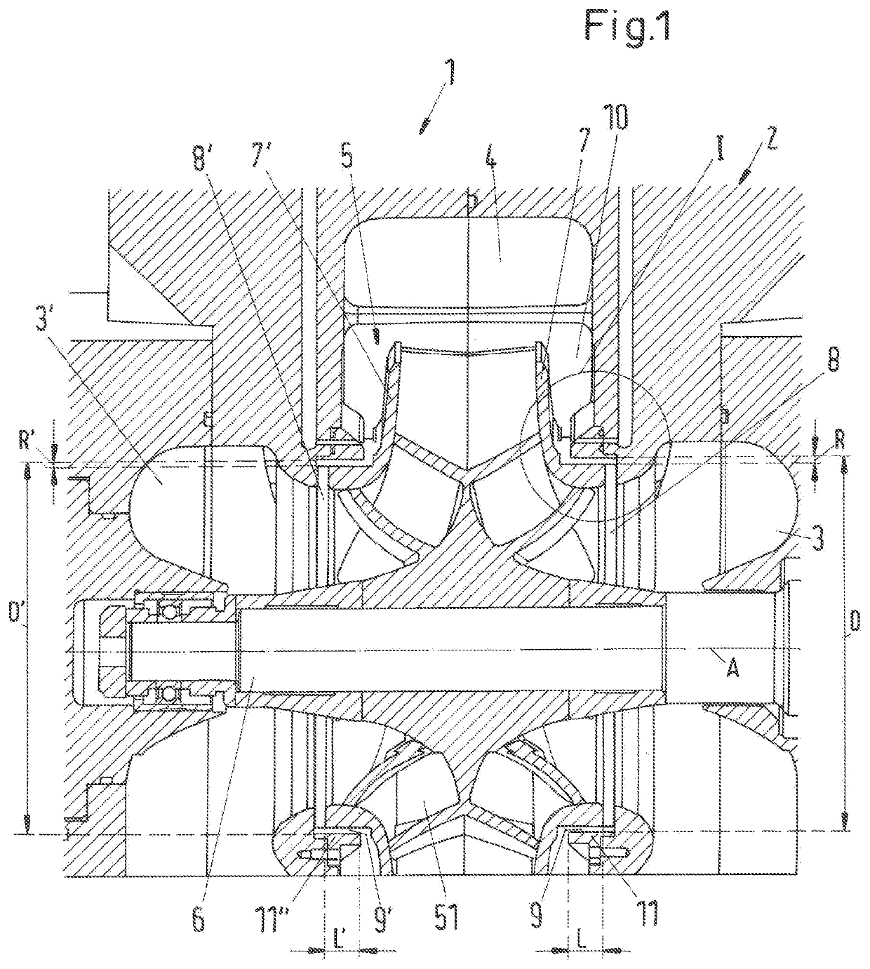
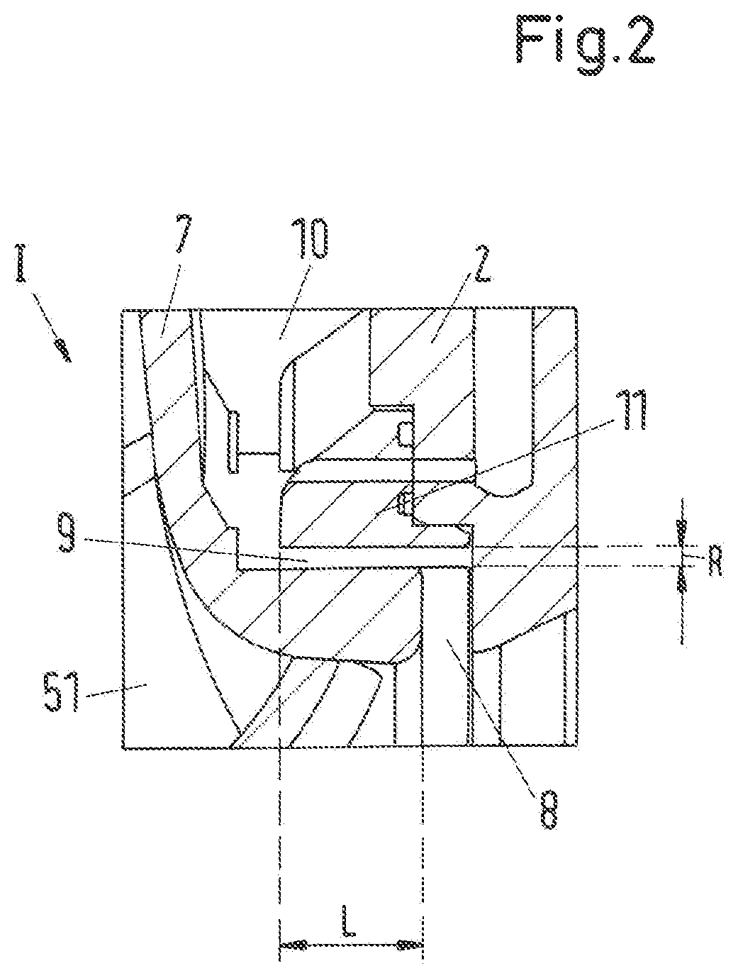
[0044]FIG. 1 shows a cross-sectional view of an embodiment of a pump according to the invention which is designated in its entity with reference numeral 1. FIG. 2 shows an enlarged representation of detail I in FIG. 1. The pump 1 is designed for conveying a highly viscous fluid, whereas the term “highly viscous” has the meaning that the kinematic viscosity of the fluid is at least 10−4 m2 / s, which is 100 centistokes (cSt).

[0045]In this embodiment the pump 1 is designed as a double suction single stage centrifugal pump. This design is one preferred embodiment which is in practice useful for many applications. Of course, the invention in not restricted to this design. A pump according to the invention may also be designed as a single suction centrifugal pump or as a multistage centrifugal pump or as any other type of centrifugal pump. Based upon the description of the embodiment shown in FIG. 1 and FIG. 2 it is no problem for the skilled person to build a pump according to the inventi...


PUM


Abstract

A pump for conveying a highly viscous fluid includes a casing with at least a first inlet and an outlet for the fluid, and an impeller for conveying the fluid from the inlet to the outlet. The impeller is arranged on a rotatable shaft for rotation around an axial direction, and includes a front shroud facing the first inlet of the pump. The casing includes a stationary impeller opening for receiving the front shroud of the impeller and has a diameter. The front shroud and the stationary impeller opening form a gap having a width in a radial direction perpendicular to the axial direction, and the ratio of the width of the gap and the diameter of the impeller opening is at least 0.0045.

Description

CROSS-REFERENCE TO RELATED APPLICATIONS[0001]This application claims benefit to European Application No. 15189843.4, filed Oct. 14, 2015, the contents of which is hereby incorporated herein by reference.BACKGROUND[0002]Field of the Invention[0003]The invention relates to a pump for conveying a highly viscous fluid.[0004]Background of the Invention[0005]Pumps for pumping highly viscous fluids are used in many different industries, for example in the oil and gas processing industry for conveying hydrocarbon fluids. Here, these pumps are used for different applications such as extracting the crude oil from the oil field, transportation of the oil or other hydrocarbon fluids through pipelines or within refineries. But also in other industries, for example, in the food industry or the chemical industry there is often the need for conveying highly viscous fluids.[0006]The viscosity of a fluid is a measure for the internal friction generated in a flowing fluid and a characteristic property...

Claims


Application Information

Patent Timeline
Patent Type & Authority Patents(United States)
IPC IPC(8): F04D29/16F04D29/42F04D29/22F04D1/00F04D7/04
CPCF04D1/006F04D7/04F04D29/4293F04D29/2266F04D29/2294F04D29/167F04D29/2222F04D29/026F04D29/245
Inventor RODRIGUES, ARNALDO
Owner SULZER MANAGEMENT AG
Why Eureka
Try Eureka