
Four-contact magnetic switch apparatus

a technology of magnetic switch and apparatus, applied in the direction of magnetic/electric field switch, magnetic field change switch, mechanical actuation of alarms, etc., can solve the problems of unauthorized manipulation of reed switch, cost and complexity of manufacturing process, etc., and achieve the effect of lowering manufacturing costs

Active Publication Date: 2020-01-21
MAGNASPHERE
View PDF22 Cites 3 Cited by
  • Summary
  • Abstract
  • Description
  • Claims
  • Application Information

AI Technical Summary

Benefits of technology

[0006]The present invention provides high-integrity switch units, switch assemblies including the units, and complete switch apparatus including the assemblies. By virtue of the construction of these devices, high security switches may be manufactured using only a single magnetic ball switch, thus lowering manufacturing costs.

Problems solved by technology

Reed switches are subject to unauthorized manipulation through the use of a strong external defeat magnet.
This represents added cost and complexity to the manufacturing process.

Method used


Image

  • Four-contact magnetic switch apparatus
  • Four-contact magnetic switch apparatus

Examples


Embodiment Construction

Embodiment of FIGS. 1-8

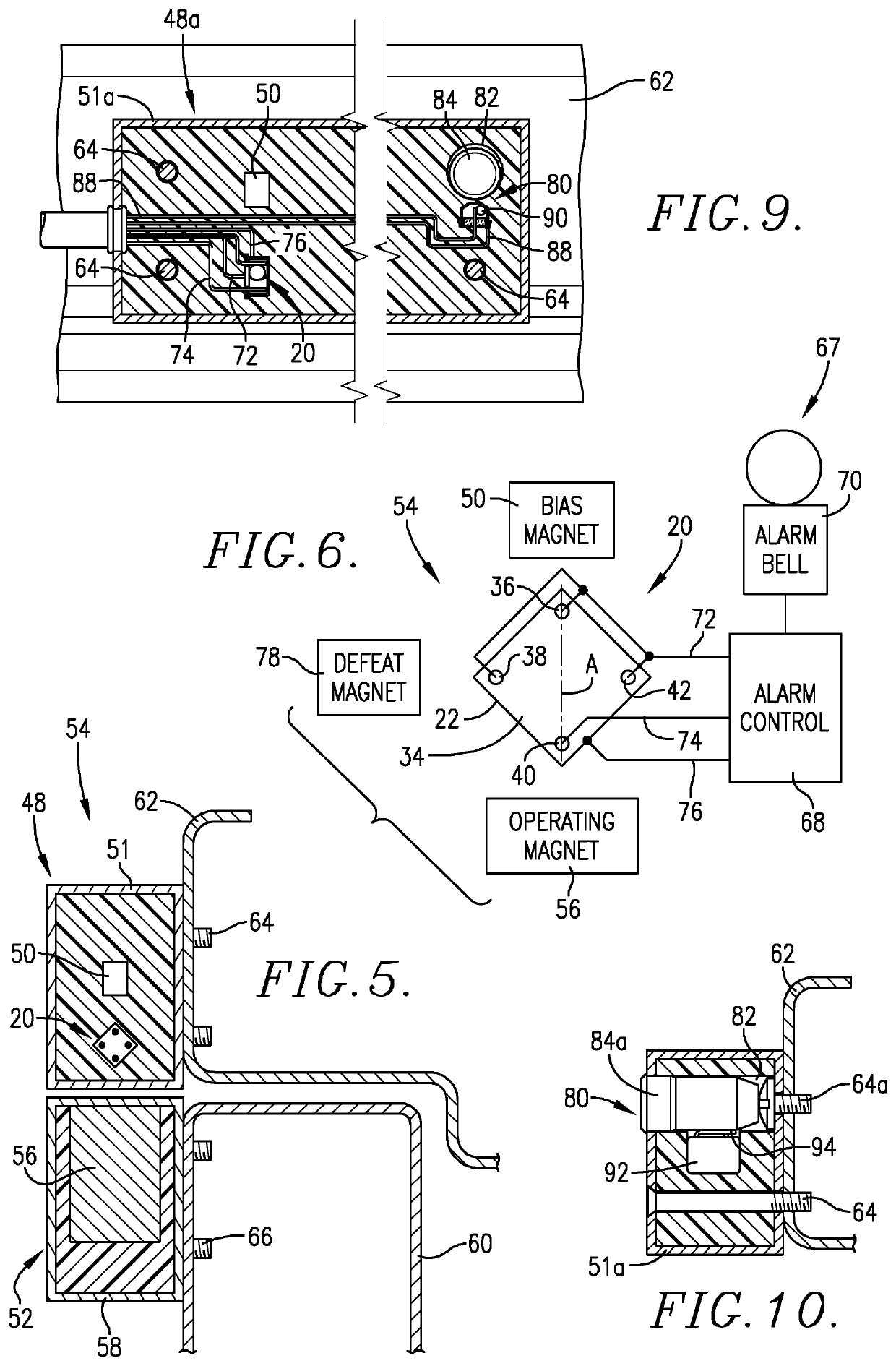
[0022]Turning now to the drawings, and particularly FIGS. 1-3 and 5-6, a switch unit 20 is illustrated and broadly includes a quadrate, integral metallic (e.g., a Cu—Ni alloy), electrically conductive housing 22 presenting four apices 24, 26, 28, 30, and an internal cavity 32; as illustrated, the housing 22 includes a base wall and upstanding sidewall structure. The unit further has a cover 34 formed of a low-magnetic susceptibility material such as stainless steel. The cover 34 is equipped with four elongated, electrically conductive contact pins 36, 38, 40, 42, such that when the cover 34 is installed on the open end of housing 22, the pins 36-42 are respectively located in proximity to the apices 24-30 (see FIGS. 7-8). As further illustrated, each pin is secured to the cover 34 by means of adhesive or ceramic material 44, and extends through the cover 34 to permit electrical connection thereof, as will be described. The switch unit also has a shiftable, ele...


PUM


Abstract

Switch apparatus (54), designed to detect relative movement between first and second members (60, 62), includes a switch assembly (48) comprising a switch unit (20), a biasing element (50), and an operating member (52). The unit (20) has a conductive housing (22) with first, second, and third electrical pin contacts (36-40) and a shiftable body (46). The body (46) is magnetically correlated with both the element (50) and operating member (52). When the members (60, 62) are close, the operating member (52) maintains the shiftable body (46) in one switch position, whereas when the members (60, 62) are separated, the biasing element (50) magnetically moves body (46) to another switch position, thereby detecting the relative movement).

Description

CROSS-REFERENCE TO RELATED APPLICATION[0001]This application claims the benefit of U.S. provisional patent application Ser. No. 62 / 603,216 filed May 22, 2017, entitled HIGH SECURITY SWITCH, which is incorporated herein by reference in its entirety.BACKGROUND OF THE INVENTIONField of the Invention[0002]The present invention is directed to improvements in magnetic ball switches. More particularly, the invention is concerned with improved switch units, switch assemblies including the units, and complete switch apparatus made up of the switch assemblies together with operating members. The switch technology of the invention provides low cost, high reliability switches, which can be used to good effect in high security protective devices.Description of the Prior Art[0003]Prior art alarm systems use magnetic switches attached to doors and / or windows for detecting unauthorized opening thereof. One common type of switch used in these systems is a so-called reed switch. Reed switches are sub...

Claims


Application Information

Patent Timeline
Patent Type & Authority Patents(United States)
IPC IPC(8): H01H1/16H01H36/00G08B13/08
CPCH01H36/00G08B13/08H01H1/16H01H2239/032H01H2205/016H01H2036/0086H01H2225/008H01H36/0033H01H36/0046H01H36/008
Inventor WOODS, CHRISTOPHERWOODS, RANDALLHEDEEN, JOSEPH C.
Owner MAGNASPHERE
Learn More