Deployable, forward looking range sensor for command detonation

a command and range sensor technology, applied in the field of guided munitions, can solve the problems of difficult time accuracy and total ineffective movement of targets, and achieve the effect of improving the accuracy of the detonation

Active Publication Date: 2020-01-14
BAE SYST INFORMATION & ELECTRONICS SYST INTERGRATION INC
View PDF21 Cites 4 Cited by
  • Summary
  • Abstract
  • Description
  • Claims
  • Application Information

AI Technical Summary

Benefits of technology

The patent is about a method for guiding a projectile by using a range finder to determine the distance between the projectile and its target. The method involves starting a clock when the first signal is detected and stopping it when the second signal is detected. This creates a time difference that represents the round-trip time between the projectile and the target, which can be converted into a range-to-go. Additional accuracy can be achieved by measuring the time expansion between the first and second signals and convolving the projectile's velocity with it. The technical effect of this invention is an improved accuracy in guiding the direction of a projectile towards its target.

Problems solved by technology

In either case, knowing the time accurately has been difficult.
However, these and other techniques rely on knowing the range to extreme accuracy prior to launch and are totally ineffective for moving targets.

Method used


Image

  • Deployable, forward looking range sensor for command detonation
  • Deployable, forward looking range sensor for command detonation
  • Deployable, forward looking range sensor for command detonation

Examples


Embodiment Construction

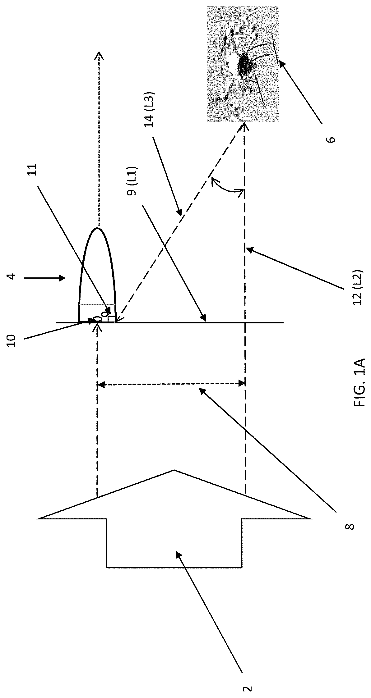
[0022]One embodiment of the present disclosure is a system for accurately determining the range-to-target distance for a guided munition. In one embodiment, the accuracy is within less than a meter. In some cases, the system utilizes a low energy, short pulse laser (e.g., fiber laser) or radio frequency pulse to paint a target. The short pulse can be 1 to 50 nanoseconds depending on the transmitter. In some cases, the system is low power since the path is one way from the illuminator to the projectile. In certain embodiments, low energy is about 100 μJoules per pulse.

[0023]When munitions are laser guided a target is illuminated, or “painted,” by a laser target designator on the ground or on an aircraft. One disadvantage of typical laser guided munitions is that in poor weather the system may not be useable because the target illumination cannot be seen, or if the target designator cannot get near the target. In certain embodiments, a laser designator sends a beam in a coded series o...


PUM


Abstract

The system and method for accurately determining range-to-go for the time-delayed command detonation of a projectile. Using dual laser and / or radio frequency detectors on a spinning projectile to determine the range-to-go, time-to-go, or lateral offset from the projectile to the target. The detectors are forward facing and rear facing and are located in a tail kit such that cost can be greatly reduced on a spinning projectile. The deployable detector(s) may be a light pipe, mirrors, or the like and comprise APD or PIN diodes.

Description

FIELD OF THE DISCLOSURE[0001]The present disclosure relates to guided munitions and more particularly to deployable, forward looking range sensor for command detonation of a projectile.BACKGROUND OF THE DISCLOSURE[0002]Precise command detonation maximizes the warhead effects against a target and is highly depended on the “range to go” or “time to go” prior or after impact. Depending on the target and warhead fragment pattern there is an optimum distance in front of the target for soft target (UAS, aircraft, combatants, etc.). For structures, a distance “after” the target, or a delayed detonation, may be useful when flight through a window is preferred, for example. In either case, knowing the time accurately has been difficult. Many simple rounds have used spin counters and by knowing the target range and the number of revolutions / meter from the projectile rifling, one can program the round to detonate after a particular spin count. However, these and other techniques rely on knowin...

Claims


Application Information

Patent Timeline
Patent Type & Authority Patents(United States)
IPC IPC(8): F42C13/02
CPCF42C13/02F42C13/023
Inventor CHOINIERE, MICHAEL J.STOCKWELL, JASON T.
Owner BAE SYST INFORMATION & ELECTRONICS SYST INTERGRATION INC
Why Eureka
Try Eureka