Rotor arrangement for a turbomachine and compressor

a technology of turbomachines and rotors, which is applied in the direction of machines/engines, mechanical apparatus, liquid fuel engines, etc., can solve the problems of affecting the performance of the engine, the smell of oil, and the accumulation of oil, so as to reduce the cost of the engine. , the effect of reducing the cost of the engin

Active Publication Date: 2019-12-31
MTU AERO ENGINES GMBH
View PDF16 Cites 0 Cited by
  • Summary
  • Abstract
  • Description
  • Claims
  • Application Information

AI Technical Summary

Benefits of technology

[0003]An object of the present invention is to propose a rotor arrangement for a turbomachine, in which fluid accumulations can be avoided. Another object of the present invention is to propose a compressor.
[0020]In some embodiments according to the invention, a balancing device on the first hub for balancing the first rotor stage can partially or completely replace a separate balancing of the first rotor stage. A partial or complete prolongation of the balancing of the first rotor stage on the adjacent hub can be utilized advantageously for the purpose of reducing or completely preventing oil accumulations caused by centrifugal force in a rotor spool joined to the first rotor stage. These types of oil accumulations can form in cavities of the rotor spool, if, for example, balancing frets or balancing flanges on the inner side of the rotor spool prevent or limit an outflow of oil into oil overflow boreholes. Oil overflow boreholes can be disposed, for example, in a rotor arm. Avoiding balancing devices in the structure inside the rotor spool and prolonging the balancing of the first rotor stage of a rotor arrangement according to the invention on the adjacent hub advantageously can reduce or eliminate an oil accumulation in the rotor spool.
[0027]By means of the rotor arrangement according to the invention and a prolonging of the balancing of the first rotor stage on the hub, oil accumulations, for example, accumulations of bearing oil, can be prevented advantageously inside a rotor spool formed at least by rotor stages. In particular, it makes possible the arrangement of a balancing ring on the radially outer side of a rotor arm, so only small cavities or in general no cavities in which oil can accumulate can form in the rotor spool. In the case of an application of the rotor spool in an aircraft engine, the possibility or danger of contaminations or an oil odor in the cabin air of airplanes due to bearing oil or bearing-oil vapor can at least be reduced thereby. Bearing oil or bearing-oil vapor in a rotating rotor spool according to the invention can be directly transported into the primary flow of the stator and rotor blading through an opening on the radius of the inner contour of the rotor spool and passed on to the discharge from the turbomachine. A possible danger of fire due to the oil can also at least be reduced based on this rapid off-transport. An accumulation of oil and / or a condensing of oil vapor during a shutdown of the rotor spool with possible subsequent transport of the oil from the main flow into branch lines for the bleed or tapped air, e.g., for the cabin air in airplanes, advantageously can be prevented.
[0028]The rotor arrangement according to the invention can be utilized in turbines and / or compressors. By means of positioning the balancing devices in the outside space of the rotor and / or on an adjacent hub, the structural space and the weight of the rotor spool can be optimized advantageously. Economic advantages can result thereby, for example, due to lower fuel consumption and / or a compact structural shape.
[0029]An arrangement of the balancing ring outside the rotor spool, and thus an arrangement on a larger diameter in comparison to an arrangement of the balancing ring inside the rotor spool, can lead to a reduction in mass and in the weight of a flange arrangement (arrangement for the flange mounting of another rotor in form-fitting manner). This can advantageously lead to a reduction in the weight of the rotor.
[0030]The rotor arrangement according to the invention makes possible a balancing directly on the hub, which joins individual rotors to a shaft, in particular, the rotor disks of a multi-stage rotor assembly disposed at the upstream and downstream ends. A balancing of these rotor stages joined to the hubs can advantageously be dispensed with. Thus, balancing time and expenditure for balancing can be reduced overall, and thus time and cost can be advantageously reduced.

Problems solved by technology

For example, after the rotor starts up again, oil can be distributed as a liquid into regions of the turbomachine that bring about considerable disadvantages for such oil accumulation.
In one possible use of the turbomachine as an aircraft engine, the oil can enter into the cabin air via ducts in the casing when the rotors start up again and this leads to the smell of oil and contaminations therein.

Method used


Image

  • Rotor arrangement for a turbomachine and compressor

Examples


Embodiment Construction

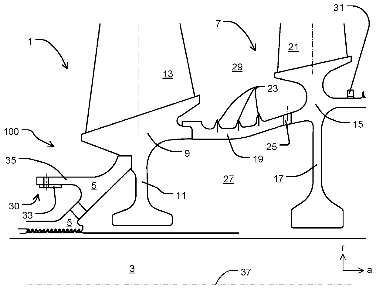
[0033]FIG. 1 shows a rotor arrangement 100 according to the invention having a first rotor stage 1, a shaft 3, and a hub 5, as well as a second rotor stage 7. The direction of through-flow of the rotor corresponds to the axial direction a. Additional coordinate axes are the radial direction r and the peripheral direction u.

[0034]The first rotor stage 1 comprises a first basic rotor body 9 having a radially inwardly directed first rotor disk 11 and an integrally joined first blade 13. The first basic rotor body 9 is joined upstream (left in FIG. 1) in form-fitting manner to the hub 5 and downstream (right in FIG. 1) in form-fitting manner to the second rotor stage 7.

[0035]The second rotor stage 7 comprises a second basic rotor body 15 with a radially inwardly directed second rotor disk 17, a spool-shaped rotor arm 19 and an integrally joined second blade 21. The second basic rotor body 15 is joined upstream in form-fitting manner to the first basic rotor body 9 by means of the rotor ...


PUM


Abstract

The present invention relates to a rotor arrangement for a turbomachine, having a rotor with a first rotor stage, a shaft, and a first hub for joining the first rotor stage to the shaft. The first hub has a balancing device for balancing the first rotor stage. In addition, the present invention relates to a compressor.

Description

BACKGROUND OF THE INVENTION[0001]The present invention relates to a rotor arrangement for a turbomachine and compressor claimed herein.[0002]In rotors for turbomachines, in specific situations during operation, accumulations of liquids are formed in cavities of rotor spools due to centrifugal force during the operation of rotors. This accumulated liquid can flow into another region of the rotors only when the rotors are shut down and may cause various disadvantages. For example, after the rotor starts up again, oil can be distributed as a liquid into regions of the turbomachine that bring about considerable disadvantages for such oil accumulation. In one possible use of the turbomachine as an aircraft engine, the oil can enter into the cabin air via ducts in the casing when the rotors start up again and this leads to the smell of oil and contaminations therein.SUMMARY OF THE INVENTION[0003]An object of the present invention is to propose a rotor arrangement for a turbomachine, in wh...

Claims


Application Information

Patent Timeline
Patent Type & Authority Patents(United States)
IPC IPC(8): F01D5/02F01D5/06F01D5/34F01D25/00F04D29/32F04D29/70
CPCF04D29/321F01D5/027F01D5/06F01D5/34F01D25/002F04D29/701F05D2240/24F05D2220/32F05D2240/60F05D2220/3219Y02T50/60
Inventor BOEWING, STEFAN
Owner MTU AERO ENGINES GMBH
Why Eureka
Try Eureka