Capping assembly for inkjet printhead

a technology of inkjet printhead and assembly, which is applied in the direction of engine seals, printing, bellows, etc., can solve the problems of inevitable vapor loss, reduce ink usage, mitigate the deleterious effects of pressure differences, and minimize vapor loss

Active Publication Date: 2019-12-31
MEMJET TECH LTD
View PDF2 Cites 3 Cited by
  • Summary
  • Abstract
  • Description
  • Claims
  • Application Information

AI Technical Summary

Benefits of technology

[0010]As foreshadowed above, the relative pressure differences may be due to a number of factors, such as changes in atmospheric pressure or temperature changes affecting the pressure inside the capping volume. Advantageously, the capping assembly according to the first aspect equalizes pressures inside and outside the capping volume without requiring a breather hole. Consequently, the capping assembly advantageously minimizes vapor losses from the capping volume when the printhead is capped, whilst mitigating against the deleterious effects of pressure differences e.g. capper suctioning, nozzle deprime, nozzle flooding etc. Accordingly, nozzle health in the printhead is optimized during capped periods and remedial measures after uncapping may be minimized, resulting in reduced ink usage and / or shorter printer wake-up times. The capping assembly is particularly suitable for pagewide printheads in which optimum nozzle health is crucial for single-pass printing so as to avoid print quality defects. However, it will be appreciated that the capping assembly may be used in any suitable inkjet printhead.

Problems solved by technology

However, even with such measures, a degree of vapor loss is inevitable over long periods and it would be desirable to minimize vapor losses even further whilst still allowing facile capping and uncapping.

Method used


Image

  • Capping assembly for inkjet printhead
  • Capping assembly for inkjet printhead
  • Capping assembly for inkjet printhead

Examples


Embodiment Construction

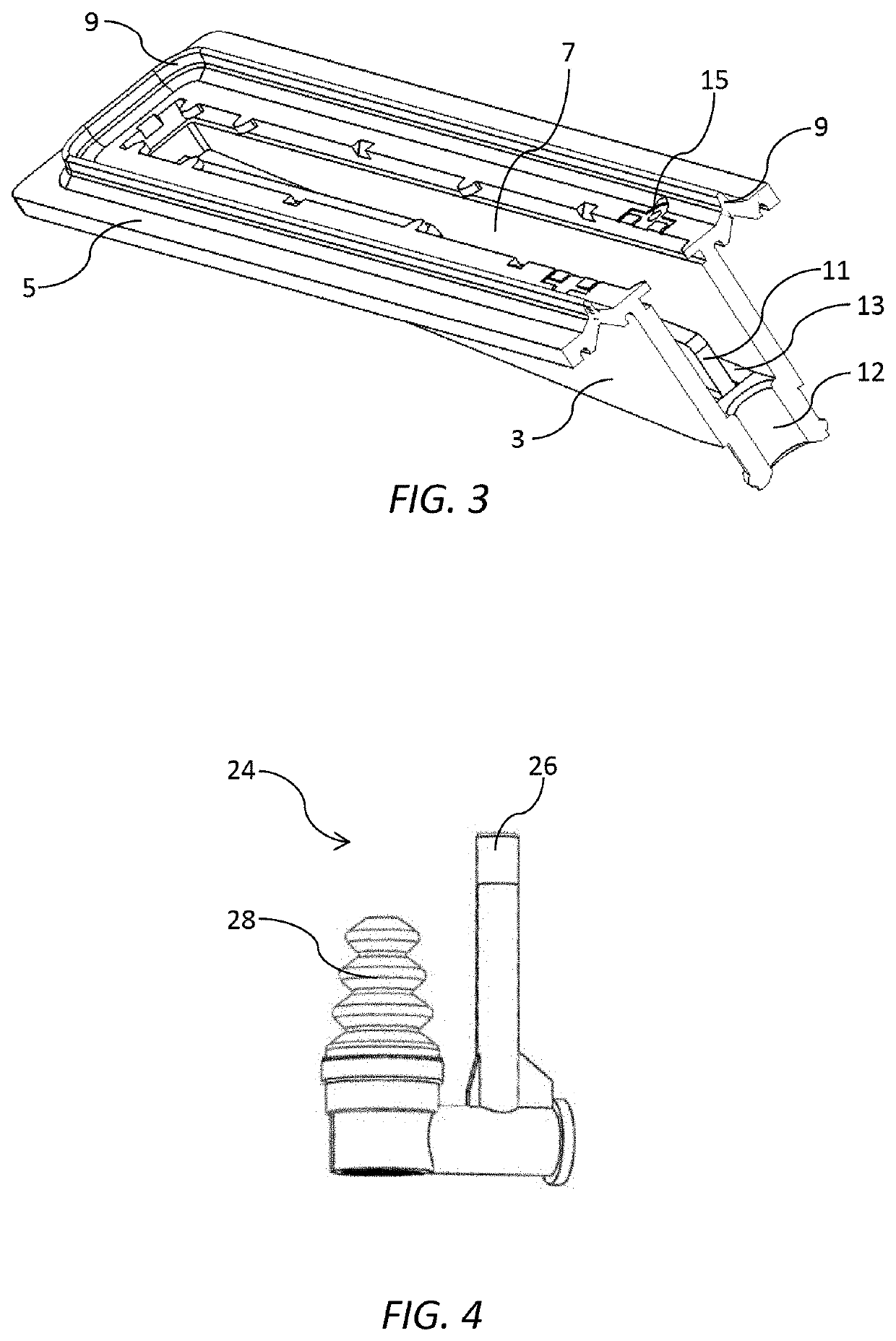
[0033]Referring to FIGS. 1 to 3, there is shown a capper 1 for capping a pagewide printhead. The capper 1 comprises a rigid capping chamber 3 having a perimeter lip 5 surrounding a mouth 7 of the chamber. A perimeter seal 9 comprised of a compliant material (e.g. elastomer) is fixed to the perimeter lip 5 of the capping chamber 3. The perimeter seal 9 is configured for engagement with a surface of a printhead (not shown in FIGS. 1 to 3) as is well known in the art.

[0034]As shown in FIG. 3, the capping chamber 3 is generally elongate and has an elongate strip of an absorbent material 11 attached to a floor 13 of the chamber. In use, the absorbent material 11 may act as a spittoon by receiving ink droplets ejected from the printhead. The ink retained by the absorbent material 11 assists in maintaining a humid environment within the capping chamber 3 when the printhead is capped. Excess ink within the capping chamber 3 may be drained, either using gravity or suitable pump, via a draina...


PUM


Abstract

A capping assembly includes a capper having a perimeter seal for sealing engagement with the printhead. The capping assembly has an enclosed capping volume when the capper is sealingly engaged with the printhead, whereby the capping volume is variable in response to relative differences in pressures inside and outside the capping volume.

Description

CROSS-REFERENCE TO RELATED APPLICATIONS[0001]The present application claims the benefit of priority under 35 U.S.C. § 119(e) of U.S. Provisional Application Ser. No. 62 / 459,513, entitled CAPPING ASSEMBLY FOR INKJET PRINTHEAD, filed Feb. 15, 2017, the content of which is hereby incorporated by reference in its entirety for all purposes.FIELD OF THE INVENTION[0002]This invention relates to a capping assembly for an inkjet printhead. It has been developed primarily to provide a robust seal for an inkjet printhead with minimal vapor losses, whilst facilitating capping and uncapping operations.BACKGROUND OF THE INVENTION[0003]The Applicant has developed a range of Memjet® inkjet printers as described in, for example, WO2011 / 143700, WO2011 / 143699 and WO2009 / 089567, the contents of which are herein incorporated by reference. Memjet® printers employ one or more stationary inkjet printheads in combination with a feed mechanism which feeds print media past the printhead in a single pass. Memj...

Claims


Application Information

Patent Timeline
Patent Type & Authority Patents(United States)
IPC IPC(8): B41J2/165F16J15/04F16J3/04
CPCB41J2/16511F16J3/04F16J15/04B41J2002/16514B41J2/16508B41J2/16523B41J2/16585
Inventor MCAULIFFE, PATRICK
Owner MEMJET TECH LTD
Why Eureka
Try Eureka