
Drying expiratory limb with tailored temperature profile and multi-lumen configuration

a technology of expiratory limbs and temperature profiles, applied in the field of respirator circuits, can solve the problems of increased gas loss, increased gas loss, and increased gas loss, and achieve the effect of increasing the gas drying

Active Publication Date: 2019-12-10
FISHER & PAYKEL HEALTHCARE LTD
View PDF8 Cites 2 Cited by
  • Summary
  • Abstract
  • Description
  • Claims
  • Application Information

AI Technical Summary

Benefits of technology

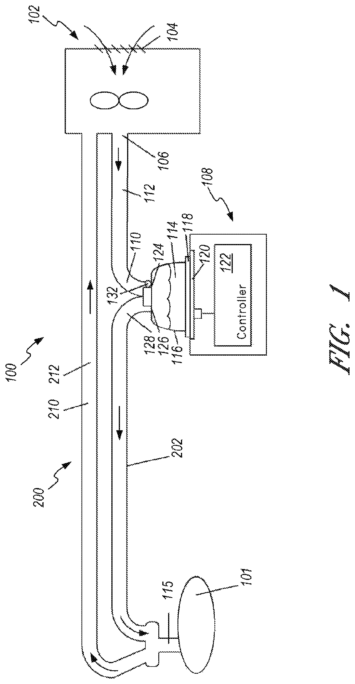
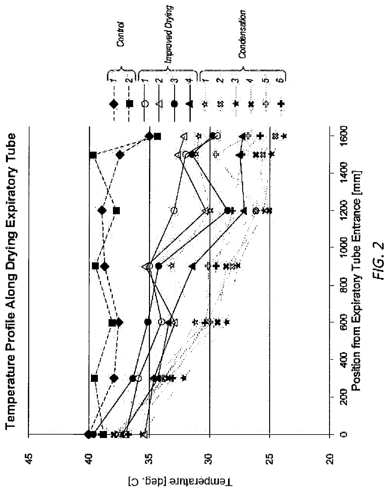
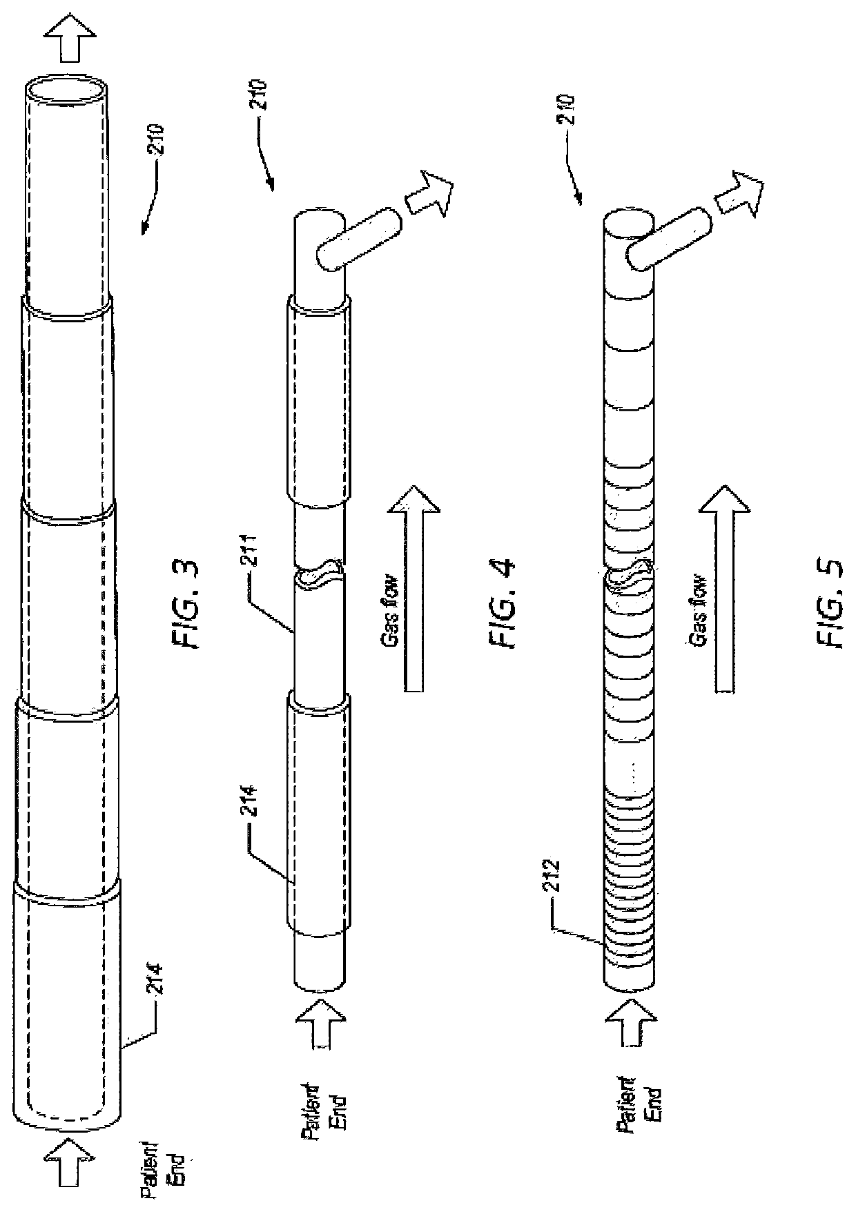
The patent describes a drying expiratory limb for use in a respiratory circuit. The drying expiratory limb is designed to increase the drying of gas as it passes through the limb, reduce or prevent rain out in the tube, and reduce or eliminate condensation in the ventilator. The temperature profile of the gas is controlled to maintain a constant difference between the gas temperature and its dew point temperature. The drying expiratory limb can be designed to improve breathability by increasing the cross-section of the limb or decreasing the flow rate. The multi-lumen design has a higher drying capacity compared to a single lumen of a similar size and material. Overall, the drying expiratory limb improves the drying process and prevents issues in the respiratory circuit.

Problems solved by technology

Condensation, or “rain out,” can be a problem when the high humidity gases come into contact with the walls of a component at a lower temperature.
In addition, condensation may occur where the exhaled gases enter the ventilator.
Such condensation is particularly deleterious when it is in close proximity to the patient.
For instance, mobile condensate forming in a breathing limb (either inspiratory or expiratory) can be breathed or inhaled by a patient and may lead to coughing fits or other discomfort.
Increasing the surface area of the expiratory limb can increase drying, but it can also increase heat loss, which can lead to rain out.

Method used


Image

  • Drying expiratory limb with tailored temperature profile and multi-lumen configuration
  • Drying expiratory limb with tailored temperature profile and multi-lumen configuration
  • Drying expiratory limb with tailored temperature profile and multi-lumen configuration

Examples


Embodiment Construction

[0056]Certain embodiments and examples of expiratory limbs are described herein. Those of skill in the art will appreciate that the disclosure extends beyond the specifically disclosed embodiments and / or uses and obvious modifications and equivalents thereof. Thus, it is intended that the scope of the disclosure not be limited by any particular embodiments described herein.

[0057]Descriptions of expiratory limbs are presented herein that include breathable material configured to pass water vapor and to substantially prevent liquid water from passing through. Any suitable breathable material can be used. As an example, sample breathable materials are described in Applicant's PCT Publication WO 2011 / 077250, entitled “Components for Medical Circuits,” filed Dec. 22, 2010, which is hereby incorporated by reference in its entirety and made a part of this specification. For example, the breathable material can be a breathable foamed material configured to allow the transmission of water va...


PUM


Abstract

A drying expiratory limb of a breathing circuit is provided that is configured to increase or optimize drying of a gas to reduce or prevent condensation. The drying expiratory limb can include a wall that is at least partly made of a breathable material configured to allow transmission of water vapor but substantially prevent transmission of liquid water. The wall includes first and second openings in the wall, the openings respectively configured to receive a gas at a first temperature and a first relative humidity and to allow the gas to exit having a second temperature and a second relative humidity. The drying expiratory limb can be configured to tailor the temperature drop of the gas along the wall to maintain a relative humidity within a targeted range and / or to maintain the gas temperature above its dew point temperature.

Description

CROSS-REFERENCE TO RELATED APPLICATIONS[0001]This application is the U.S. national phase of International Application No. PCT / NZ2014 / 000038, filed Mar. 14, 2014, which claims the benefit of U.S. Provisional Application No. 61 / 790,424, entitled “DRYING EXPIRATORY LIMB WITH TAILORED TEMPERATURE PROFILE,” filed Mar. 15, 2013, and U.S. Provisional Application No. 61 / 789,754, entitled “DRYING EXPIRATORY LIMB WITH TAILORED TEMPERATURE PROFILE AND MULTI-LUMEN CONFIGURATION,” filed Mar. 15, 2013, each of which is incorporated by reference herein in its entirety.BACKGROUND[0002]Field[0003]This disclosure relates generally to expiratory limbs for use in respiratory circuits, and in particular to a breathing circuit with an improved drying expiratory limb configured to provide improved drying performance by providing a tailored temperature profile along the tube.[0004]Description of Related Art[0005]In medical applications, various components transport gases having high levels of relative humi...

Claims


Application Information

Patent Timeline
Patent Type & Authority Patents(United States)
IPC IPC(8): A61M16/00A61M16/16A61M16/10A61M16/08
CPCA61M16/0808A61M16/161A61M16/0883A61M16/1095A61M16/0875A61M2205/3368A61M2205/0238A61M2205/3673A61M2205/3633A61M2205/33A61M2205/50A61M16/16
Inventor MILNE, ROBERT ANDREW DAVIDGIERKE, TIMOTHY DEE
Owner FISHER & PAYKEL HEALTHCARE LTD
Learn More