
Nacelle for a wind turbine including a cooling circuit

a wind turbine and cooling circuit technology, applied in the direction of motors, dynamo-electric machines, engine fuctions, etc., can solve the problems of limiting the life of the turbine and the efficiency of such solutions may be lower than the efficiency obtainable, so as to prolong the life of the inlet fan, facilitate salt crystallization, and increase the residence time of the air

Active Publication Date: 2019-12-03
SIEMENS WIND POWER
View PDF17 Cites 5 Cited by
  • Summary
  • Abstract
  • Description
  • Claims
  • Application Information

AI Technical Summary

Benefits of technology

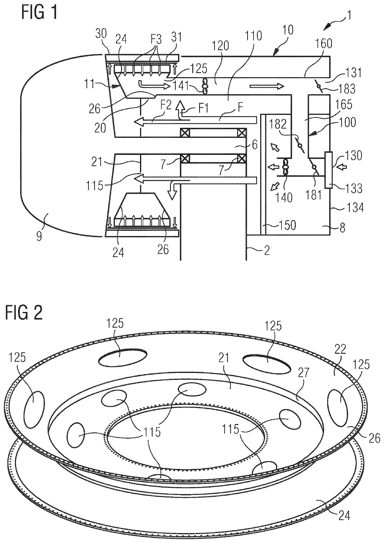
[0009]Advantageously, one or more additional holes may be provided in the stator for channeling the fluid medium heated in the air between the stator and the rotor towards the outside of the nacelle. This helps in providing compact solution both for the electrical generator and the cooling circuit.
[0014]Advantageously the fluid medium heated in the air between the stator and the rotor may be used to be mixed with the fresh cooling medium entering the nacelle. This may help in reducing the humidity percentage of the cooling medium entering the nacelle with the purpose of facilitating the formation of salt crystals in the cooling medium, to be more easily stop before they reach the electrical generator.
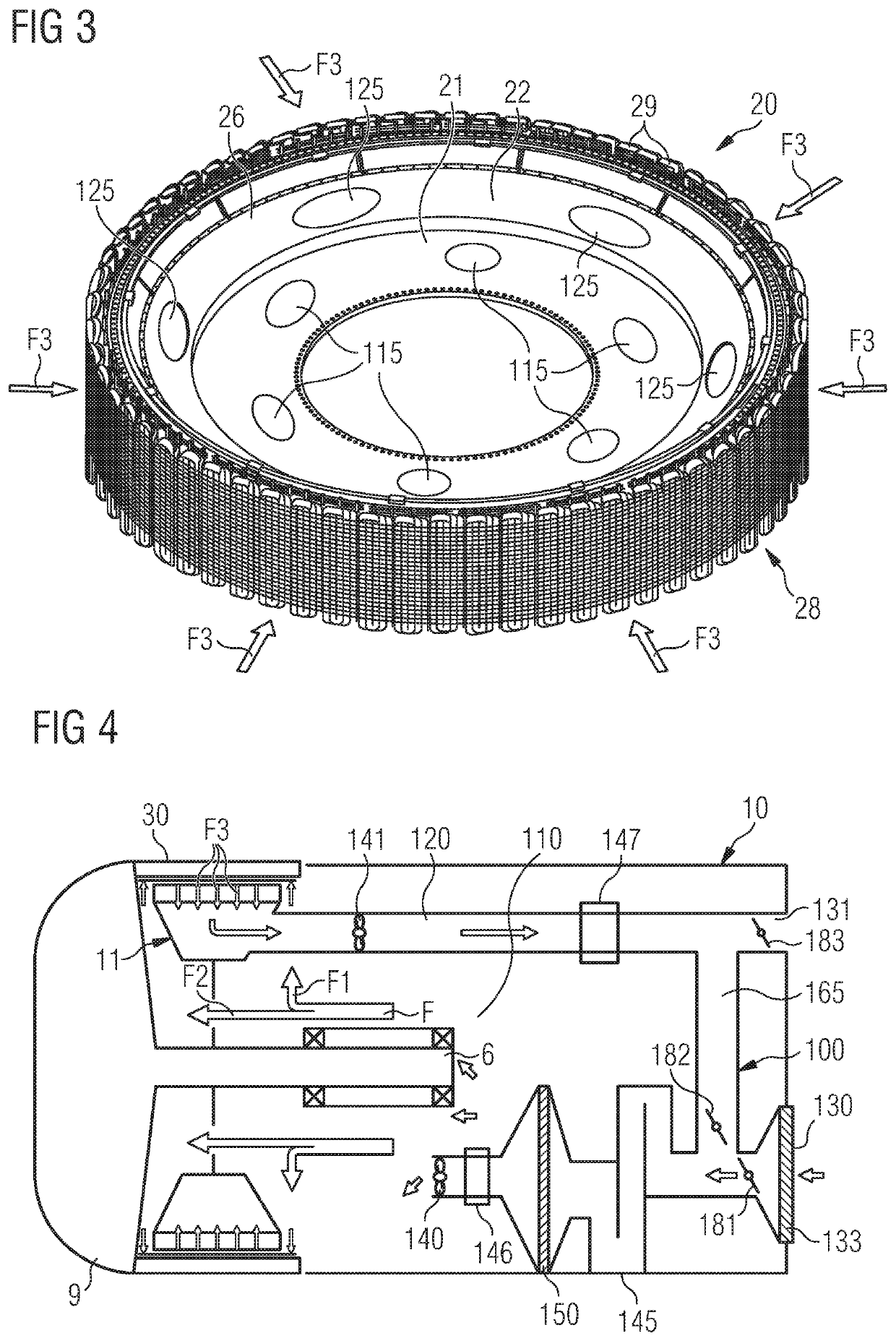
[0017]Advantageously a mixing chamber is introduced before the filter to increase the residence time of the air at a certain temperature and its mixing. This facilitates the salt crystallization. A further advantage of this layout is the position downstream the filter of the inlet fan, which is therefore not exposed to salt. This allows for an extension of the lifetime of the inlet fan and for a less expensive fan complying with a lower corrosion class environment.

Problems solved by technology

The main inconvenience of such solution is the moisture and salt content in the outside air, which causes corrosion in the generator, thus limiting its life.
The efficiency of such solution may be however lower than the efficiency obtainable by using air from the outside ambient.

Method used


Image

  • Nacelle for a wind turbine including a cooling circuit
  • Nacelle for a wind turbine including a cooling circuit

Examples


Embodiment Construction

[0025]The illustrations in the drawings are schematic. It is noted that in different figures, similar or identical elements or features are provided with the same reference signs or with reference signs, which are different from the corresponding reference signs only within the first digit. In order to avoid unnecessary repetitions elements or features which have already been elucidated with respect to a previously described embodiment are not elucidated again at a later position of the description.

[0026]FIG. 1 shows a wind turbine 1 having a nacelle 10 according to embodiments of the invention. The wind turbine 1 comprises a tower 2, which is mounted on a non-depicted fundament. The nacelle 10 is arranged on top of the tower 2. Between the tower 2 and a main body 8 of the nacelle 10 a yaw angle adjustment device is provided, which is capable of rotating the nacelle 10 around a not depicted vertical axis, which is aligned basically with the longitudinal extension of the tower 2. By ...


PUM


Abstract

A nacelle for a wind turbine includes an electrical generator having a stator and a rotor with an air gap between the stator and the rotor. The stator includes an annular support plate. A cooling circuit in the nacelle includes at least a first inlet portion for channeling a fluid cooling medium to the gap between the stator and the rotor. The first inlet portion of the cooling circuit includes at least an inlet hole on the annular support plate for letting at least a portion of the cooling medium flow towards the air gap and an inlet fan for making the fluid cooling medium flow in the inlet portion. The stator includes a circumferentially outer structure attached to the annular support plate and the cooling circuit includes at least a second outlet portion for channeling a heated fluid medium from the air gap between the stator and the rotor.

Description

CROSS-REFERENCE TO RELATED APPLICATIONS[0001]This application claims priority to European application No. EP17163103.9 having a filing date of Mar. 27, 2017, the entire contents which are hereby incorporated by reference.FIELD OF TECHNOLOGY[0002]The following relates to a nacelle for a wind turbine and therefore including an electrical generator driven by the blades of the wind turbine. The nacelle also includes a cooling circuit for channeling a cooling medium to the generator.BACKGROUND[0003]In the above described technical field, the electrical generator and in particular the stator and the rotor has to be cooled, in order to optimize its efficiency and achieve the highest possible value of generated electrical power. Various air cooling systems are known in the art for cooling the electrical generator in a nacelle for a wind turbine.[0004]One possibility is to suck the cooling air from the outside and to direct it directly towards the generator. The main inconvenience of such so...

Claims


Application Information

Patent Timeline
Patent Type & Authority Patents(United States)
IPC IPC(8): F03D9/00H02K7/18H02K1/32F03D1/06F03D80/60F03D80/80F03D9/25H02K9/02
CPCF03D1/06F03D80/82H02K1/32F03D80/60F03D80/88F03D9/25H02K7/1838H02K9/02Y02E10/721Y02E10/725Y02E10/726F05B2260/20F03D80/80H02K9/04Y02E10/72
Inventor AIROLDI, GIOVANNI
Owner SIEMENS WIND POWER
Learn More