
Programmable active matrix of electrodes

Active Publication Date: 2019-11-12
SHARP KK
View PDF16 Cites 2 Cited by
  • Summary
  • Abstract
  • Description
  • Claims
  • Application Information

AI Technical Summary

Benefits of technology

The invention is a device with integrated programming circuitry that allows for stable connection of individual electrode elements in an electrode array to control signal lines. The device can be programmed by electronically selecting one or more unit cells and charging the programming circuitry of those cells with a function line. The charging process allows for stable connection between the programming circuitry and the individual electrode elements in the cell. The method can also include discharging and re-programming the cells and performing a refresh operation to enhance stability of the programming circuitry. The technical effects of the invention are stable and efficient programming of electrode elements and reduced signal control line connections needed.

Problems solved by technology

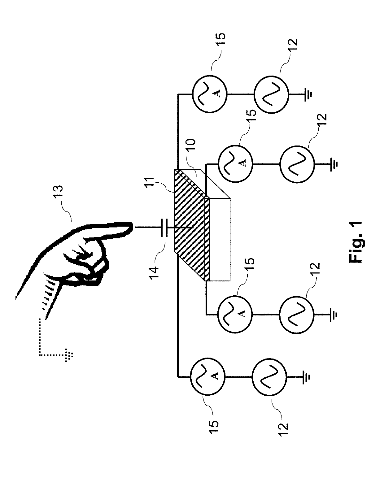
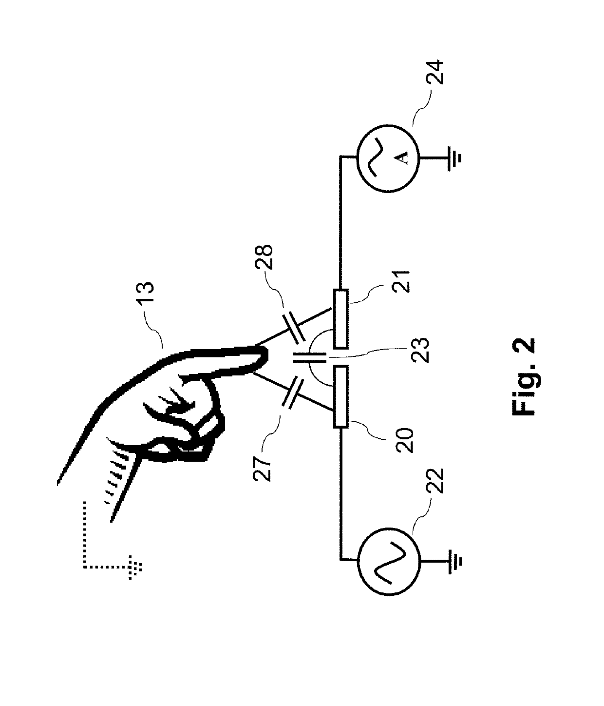
Although simple in construction and operation, surface capacitive type touch panels are unable to detect multiple simultaneous touch input events as occurs when, for example, two or more fingers are in contact with the touch panel.
In-cell touch panels, however, pose new problems, as normally the available space is very limited.
The available space for touch panel TFTs and connection lines is very limited, because most of the display area needs to be dedicated to the optical aperture for letting light through from the light source at the non-viewing side of the display system.
A single TFT potentially could be used to switch each pixel, but such a configuration would be too resistive for a touch panel element.
A deficiency of conventional systems that employ arrays of electrodes, such as for example conventional touch panels, is that the control signal connections such as driving or sensing are selectable generally upon only a row or a column basis.
Individual electrode elements generally are not individually selectable for control, and thus there are limitations on electrode control patterns which in turn may limit usage of conventional systems.

Method used


Image

  • Programmable active matrix of electrodes
  • Programmable active matrix of electrodes
  • Programmable active matrix of electrodes

Examples


Embodiment Construction

[0042]Embodiments of the present invention will now be described with reference to the drawings, wherein like reference numerals are used to refer to like elements throughout. It will be understood that the figures are not necessarily to scale.

[0043]As referenced above, the present invention is described largely in connection with an exemplary usage in touch panels. It will be appreciated that principles of this invention are applicable to other fields employing electrode arrays, being more broadly applicable to networks of switchable sensing and / or driving electrodes, such as for example display devices generally, sensors, and radio frequency (RF) antennae arrays.

[0044]Given the significant application to touch panels as a principal example, the present disclosure describes enhancements to the configuration of an electronic device that employs an array of electrodes, such as an active matrix touch panel (AMTP) including for example the AMTP configuration described in WO 2017 / 056500...


PUM


Abstract

An electrode array device has integrated programming circuitry within the unit cells for stable connection of individual electrode elements of the unit cells to one or more control signal lines. An array of unit cells are arranged in a two-dimensional array of rows and columns. Each unit cell includes an individual electrode element that is electrically connectable to at least one function line, and programming circuitry that is integrated into the unit cell and is operable to place the unit cell in a plurality of connection states corresponding to different states of electrical connection or disconnection to the at least one function line. The unit cells are individually selectable for programming and operation in one of the plurality of connection states. The programming circuitry includes storage elements and electronic switches that are operable to place the unit cells in different connection states.

Description

TECHNICAL FIELD[0001]The present invention relates to devices and applications including arrays of electrodes, and programmable arrays of electrodes in particular in which the connections of the electrode elements to external signal lines can be electrically programmed. Such type of electrode arrays may find application in a range of electronic devices and equipment, including for example touch panels, sensors, actuators, displays, and RF antennae arrays.BACKGROUND ART[0002]The present invention is described largely in connection with an exemplary usage in touch panels. It will be appreciated that principles of this invention are applicable to other fields employing electrode arrays, being more broadly applicable to networks of switchable sensing and / or driving electrodes, such as for example display devices generally, sensors, and radio frequency (RF) antennae arrays as mentioned above. Given the significant application to touch panels as a principal example, background technology ...

Claims


Application Information

Patent Timeline
IPC IPC(8): G06F3/044G06F3/041G09G3/3275G09G3/3225
CPCG09G3/3275G06F3/0416G06F3/044G06F3/0412G09G3/3225G06F3/0446G09G2310/027G06F2203/04113G09G2300/0809G06F2203/04111G06F2203/04112G06F3/04166G06F3/0443
Inventor GALLARDO, DIEGO
Owner SHARP KK
Learn More