
Delivery system for implantable medical device

a medical device and delivery system technology, applied in the field of delivery systems for implantable medical devices, can solve the problems of incomplete expansion of the device, incorrect placement of the device, and affecting the integrity of the vessel

Active Publication Date: 2019-11-05
COOK MEDICAL TECH LLC
View PDF42 Cites 1 Cited by
  • Summary
  • Abstract
  • Description
  • Claims
  • Application Information

AI Technical Summary

Benefits of technology

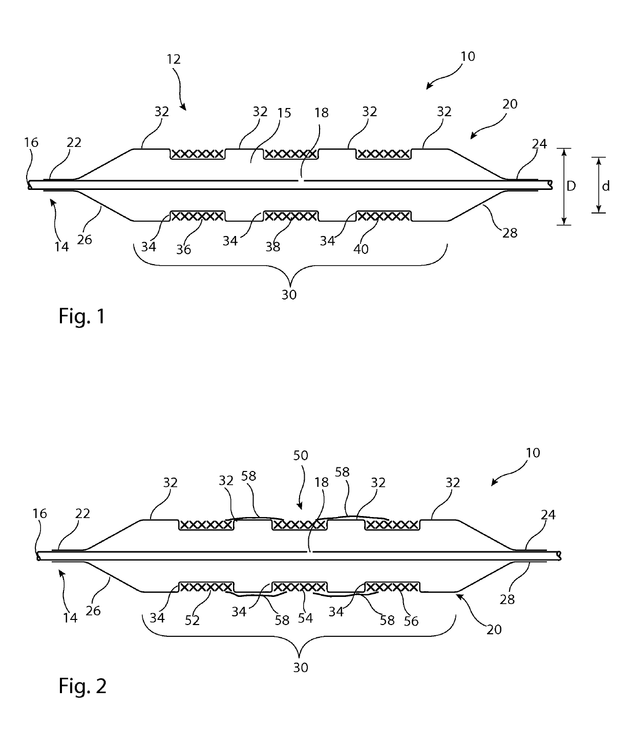
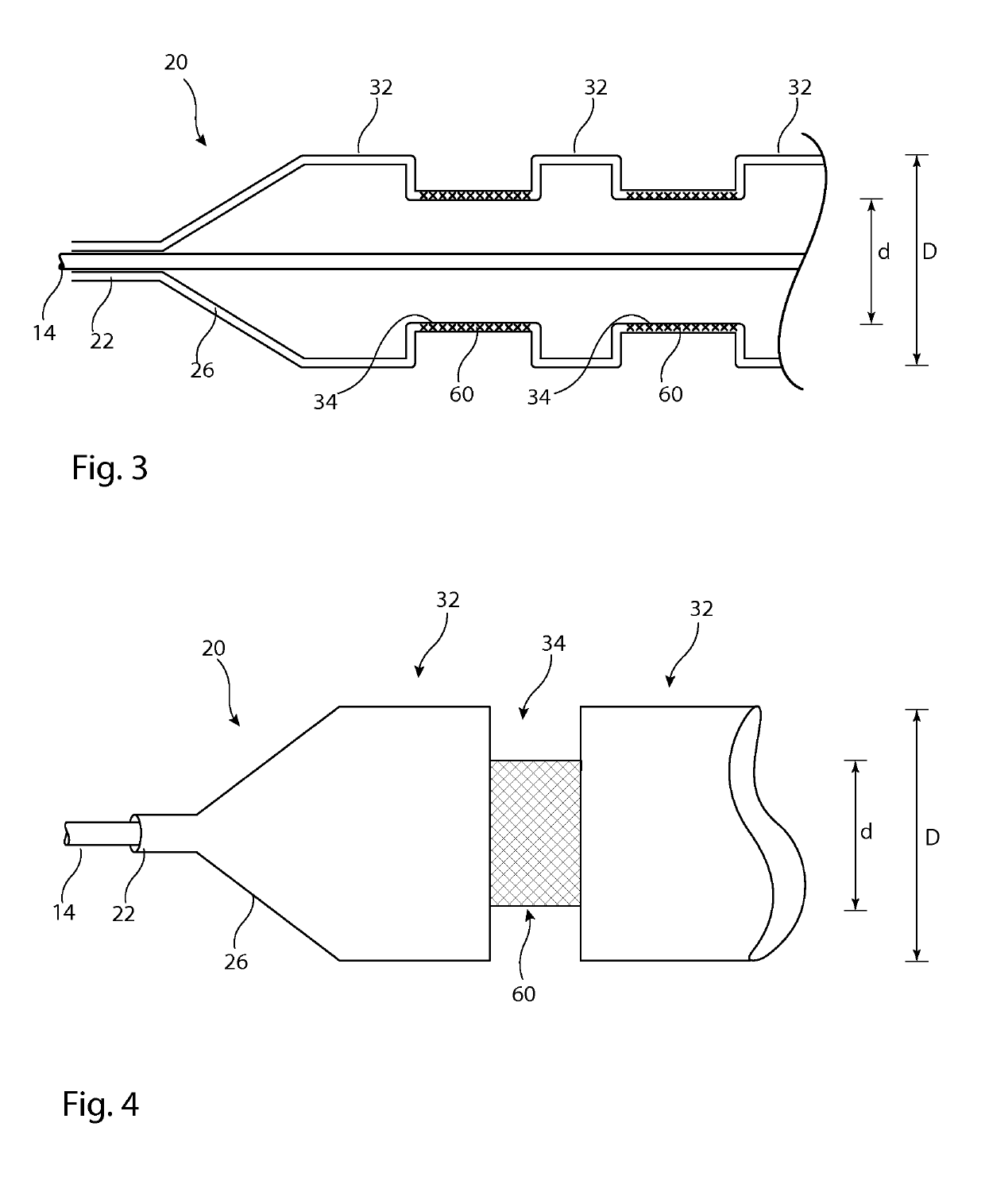
[0009]According to an aspect of the present invention, there is provided an endoluminal delivery device including: a catheter unit; a delivery balloon mounted on the catheter unit, the balloon including a body portion and first and second end portions coupled to the catheter unit, the body portion providing a medical device support surface; the delivery balloon being inflatable so as to cause the body portion to expand to an inflated diameter; and at least one circumferential constraining element disposed around at least a part of the body portion, the at least one circumferential constraining element acting to constrain inflation of at least one circumferential section of the body portion to a diameter less than the inflated diameter.
[0010]The provision of a constraining element could be said to provide a contoured or shaped delivery balloon by a mechanism opposite to that conventional in the art, namely by constraining a part of the balloon from expansion rather than by enlarging a part of the balloon. In practice, the balloon will expand under inflation pressure and will adopt a non-smooth shape as a result of the constraining elements, which non-smooth shape will provide device holding surfaces or shoulders. The shape will be retained irrespective of the degree of inflation of the balloon, that is the shape will not flatten as inflation pressure is increased, contrary to many types of conventional balloon. The constraining elements could have a relatively low volume structure which will not adversely affect the size of the delivery balloon and can also be made of flexible material so as not to impair the flexibility of the balloon particularly when in the deflated condition.
[0011]Advantageously, the or each constraining element is in the form of an annular band disposed circumferentially around the body portion. The constraining band or bands will help generate annular inflated ribs or ridges around the balloon, at the locations free of the constraining elements, useful for holding the implantable medical device in place.
[0018]The sleeve could also perform as a balloon strengthening element, allowing the balloon to be inflated to higher pressures than prior art structures.

Problems solved by technology

A problem with self-expandable devices is that in order to ensure their proper operation they are generally sized to apply constant pressure on the vessel walls, which over time can impair the integrity of the vessel.
However, there are some known issues with deployment by inflatable balloons, typically sliding of the medical device during the deployment procedure, which can lead to incorrect placement of the device in the vessel, to incomplete expansion of the device and at worst to an abortive procedure.
However, ribs and other shaping features of this nature tend to flatten on inflation of the balloon, leading to loss of the holding feature.
Such elements provide better retention of the medical device on the delivery balloon but usually at the expense of adding bulk to the balloon, which impairs its compressibility, as well as in some cases reducing its flexibility when deflated.
A less flexible and a less compressed balloon can adversely affect the trackability of the balloon through a patient's vasculature and also the size of vessel which can be treated.

Method used


Image

  • Delivery system for implantable medical device
  • Delivery system for implantable medical device
  • Delivery system for implantable medical device

Examples


Embodiment Construction

[0033]Described below are various embodiments of introducer assembly for delivering a medical device into a vessel or other organ of a patient through an endoluminal procedure from a remote percutaneous entry point. The person skilled in the art will appreciate that the drawings are schematic and intended to depict only the important features and characteristics of the apparatus and method taught herein. Some elements depicted in the drawings are not to scale or in proportion with one another in order to achieve this. The skilled person will know what dimensions and proportions are typical for such elements and devices.

[0034]Referring first to FIG. 1, this shows in cross-section an embodiment of delivery apparatus 10, upon which is mounted an implantable medical device 12. The delivery apparatus 10 includes a catheter unit 14, which in this embodiment is formed of a single catheter having at least one lumen 16 therein which is fluidically coupled to an outlet port 18. The catheter u...


PUM


Abstract

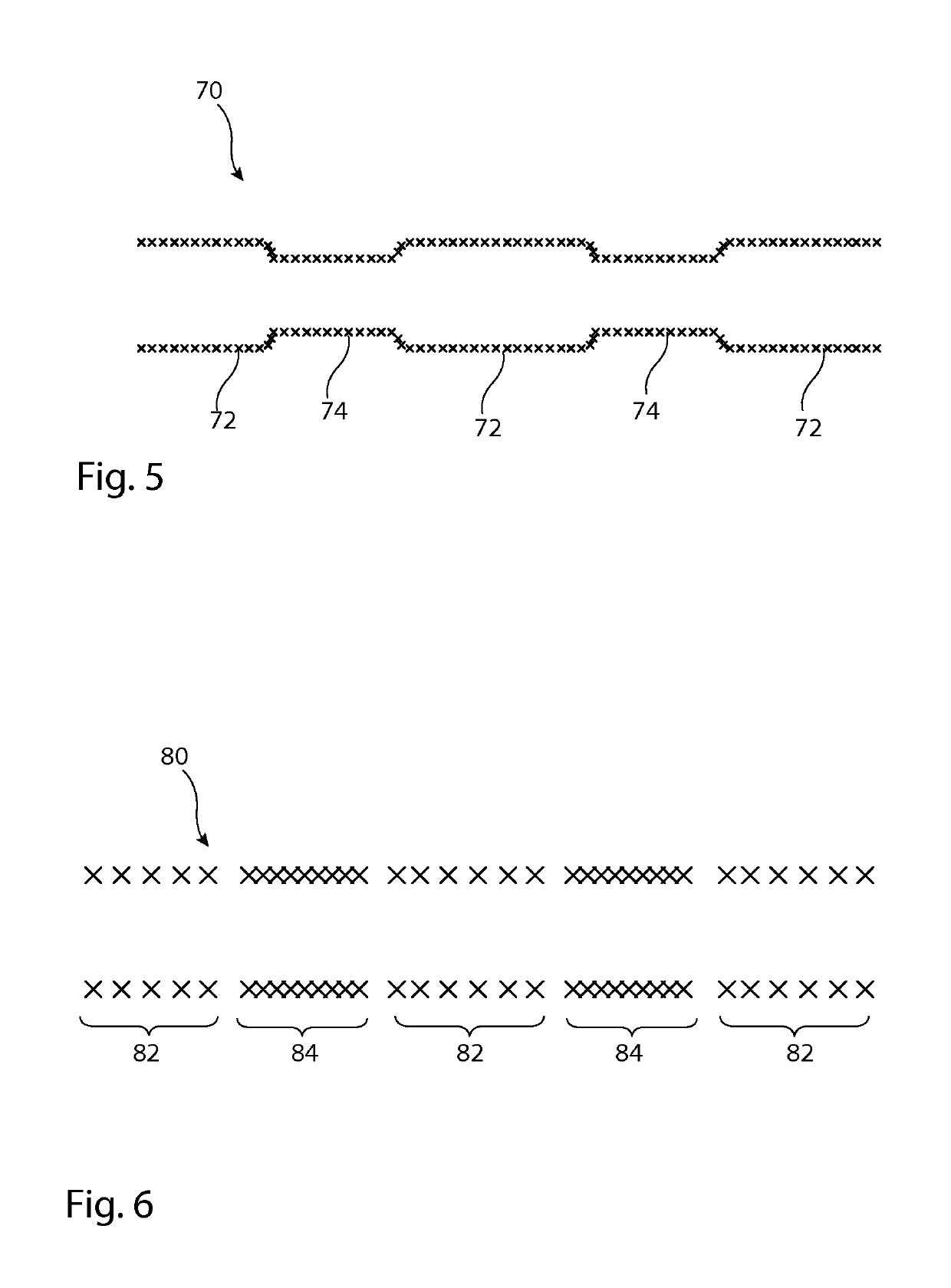
A delivery system includes an inflatable delivery balloon formed with a plurality of constraining elements which create constrained regions in a body portion of the balloon, interposed between unconstrained regions. The constrained regions create recesses for receiving a medical device or part of a medical device. The constraining elements are preferably formed by woven or braided material, advantageously embedded within the wall of the inflatable balloon. The constraining elements provide a structure that will not flatten upon inflation of the balloon and also a structure which can readily be folded or wrapped for endoluminal delivery purposes, and which retains flexibility of the delivery device.

Description

RELATED APPLICATIONS[0001]This application claims the benefit of priority under 35 U.S.C. § 119(a) to Great Britain Patent Application No. 1406404.2, filed Apr. 9, 2014, which is incorporated by reference here in its entirety.TECHNICAL FIELD[0002]The present invention relates to a delivery system for delivering an implantable medical device endoluminally into a patient's vessel and in the preferred embodiment for delivering a stent or stent graft.BACKGROUND ART[0003]Implantable medical devices are well known in the field of endoluminal treatment of medical conditions and comprise a wide variety of types. In general, medical devices are either self-expandable or expandable by a delivery mechanism of an introducer assembly. Self-expandable devices may be made of a material having inherent expansion properties, such as spring steel or other resilient material, including metals, metal alloys and also polymers and the like. Self-expandable devices may also be made of shape memory materia...

Claims


Application Information

Patent Timeline
Patent Type & Authority Patents(United States)
IPC IPC(8): A61F2/958A61F2/962
CPCA61F2/962A61F2/958A61F2230/0069A61F2250/0048A61F2002/9583A61F2210/0057A61F2002/9586A61M25/10A61M2025/1059
Inventor AGGERHOLM, STEENLYSGAARD, THOMAS
Owner COOK MEDICAL TECH LLC
Learn More