Nacelle inner lip skin with heat transfer augmentation features

a technology of inner lip and nacelle, which is applied in the direction of efficient propulsion technology, machines/engines, transportation and packaging, etc., can solve the problems of ice accumulation on the inner skin, overheating of the outer skin, and insufficient heating of the inner lip

Active Publication Date: 2019-10-29
ROHR INC
View PDF28 Cites 5 Cited by
  • Summary
  • Abstract
  • Description
  • Claims
  • Application Information

AI Technical Summary

Problems solved by technology

However, a typical prior art anti-ice system does not provide equal heating to both inner and outer skins of the inlet lip.
This can result in overheating of the outer skin and / or ice accumulation on the inner skin.

Method used


Image

  • Nacelle inner lip skin with heat transfer augmentation features
  • Nacelle inner lip skin with heat transfer augmentation features
  • Nacelle inner lip skin with heat transfer augmentation features

Examples


Embodiment Construction

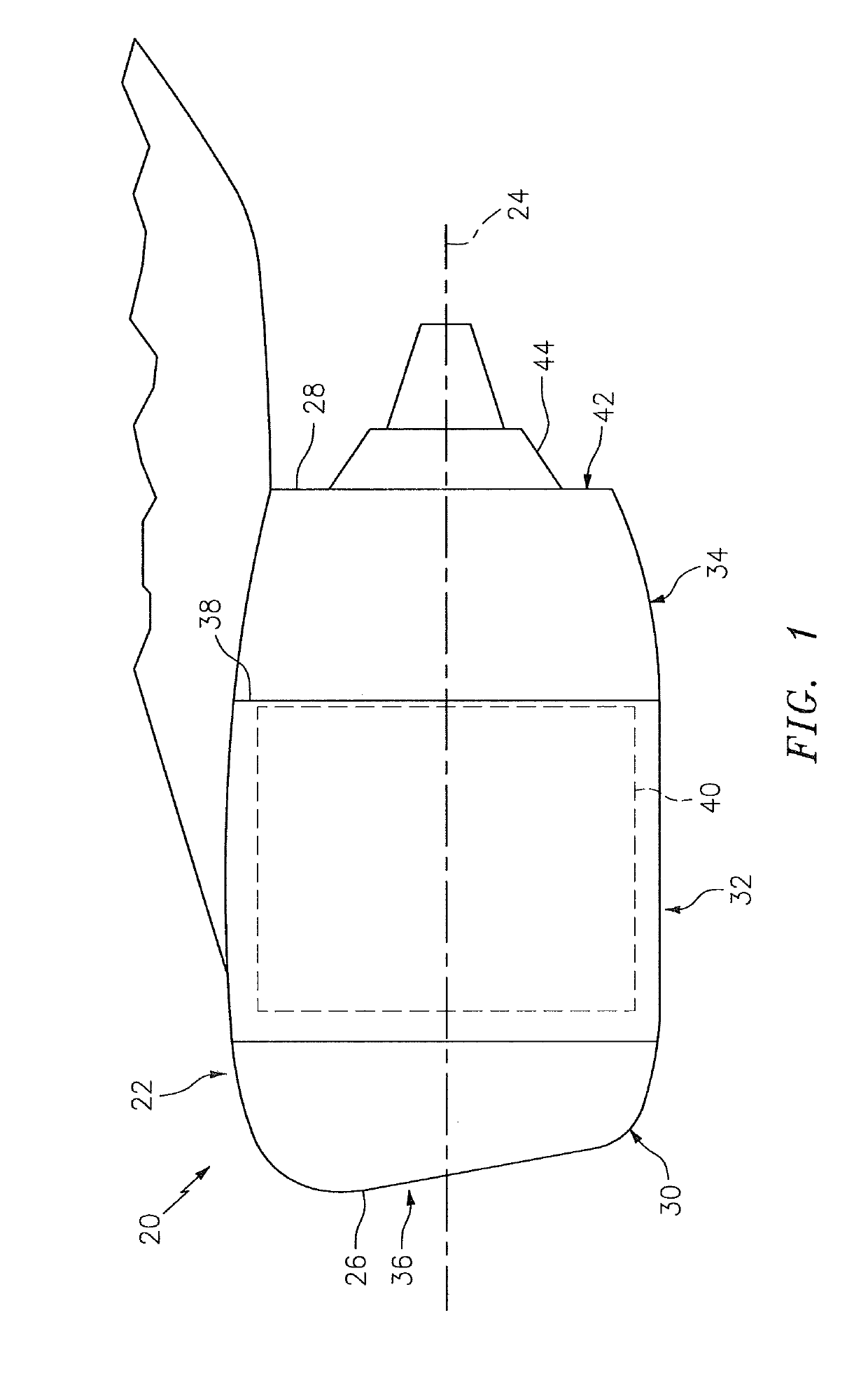
[0032]FIG. 1 illustrates an aircraft propulsion system 20 for an aircraft such as, but not limited to, a commercial airliner. The propulsion system 20 includes a nacelle 22 and a gas turbine engine. This gas turbine engine may be configured as a high-bypass turbofan engine. Alternatively, the gas turbine engine may be configured as any other type of gas turbine engine capable of propelling the aircraft during flight.

[0033]The nacelle 22 is configured to house and provide an aerodynamic cover for the gas turbine engine. The nacelle 22 extends along an axial centerline 24 between a nacelle forward end 26 and a nacelle aft end 28. The nacelle 22 of FIG. 1 includes a nacelle inlet structure 30, one or more fan cowls 32 (one such cowl visible in FIG. 1) and a nacelle aft structure 34, which may be configured as part of or include a thrust reverser system.

[0034]As discussed below in further detail, the inlet structure 30 is disposed at the nacelle forward end 26. The inlet structure 30 is...


PUM


Abstract

A nacelle inlet structure is provided for an aircraft propulsion system. This inlet structure includes an inlet lip, a bulkhead, a nozzle and a plurality of heat transfer augmentation features. The inlet lip includes an inner lip skin and an outer lip skin. The bulkhead is configured with the inlet lip to form a cavity axially between a forward end of the inlet lip and the bulkhead and radially between the inner lip skin and the outer lip skin. The annular cavity extends along a curvilinear centerline within the inlet lip. The nozzle is configured to inject fluid approximately tangentially into the annular cavity. The heat transfer augmentation features are configured with the inner lip skin and operable to interact with the fluid flow within the cavity in order to promote heat transfer between the inner lip skin and the fluid within the cavity.

Description

BACKGROUND OF THE INVENTION1. Technical Field[0001]This disclosure relates generally to an aircraft propulsion system and, more particularly, to an inlet structure of a nacelle for the aircraft propulsion system.2. Background Information[0002]A nacelle for an aircraft propulsion system may include an anti-ice system for reducing / preventing ice accumulation on an inlet lip of the nacelle. Various types and configurations of anti-ice systems are known in the art and have various benefits. However, a typical prior art anti-ice system does not provide equal heating to both inner and outer skins of the inlet lip. This can result in overheating of the outer skin and / or ice accumulation on the inner skin. There is a need in the art therefore for an improved nacelle system capable of reducing anti-ice system heat transfer rate differential between inner and outer lip skins.SUMMARY OF THE DISCLOSURE[0003]According to an aspect of the present disclosure, a nacelle inlet structure is provided ...

Claims


Application Information

Patent Timeline
Patent Type & Authority Patents(United States)
IPC IPC(8): F01D25/02B64D15/02B64D15/04F02C7/047F01D25/14B64D33/02
CPCB64D33/02B64D15/02F02C7/047F01D25/14F01D25/02B64D15/04F05D2260/2212Y02T50/675F05D2260/22141F05D2220/323F05D2260/2214Y02T50/672B64D2033/0233Y02T50/60
Inventor CHILUKURI, RADHAKRISHNA
Owner ROHR INC
Why Eureka
Try Eureka