
Image capturing apparatus

a technology of image capture and apparatus, applied in the field of photoelectric apparatus, can solve the problems of high material cost, system requires to use a large amount of optical adhesives, and no cost reduction, and achieve the effect of low cos

Active Publication Date: 2019-10-22
GINGY TECH
View PDF20 Cites 1 Cited by
  • Summary
  • Abstract
  • Description
  • Claims
  • Application Information

AI Technical Summary

Benefits of technology

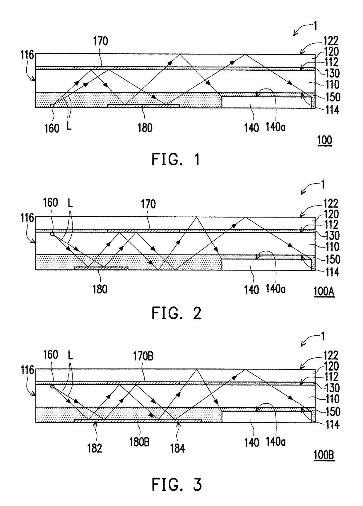
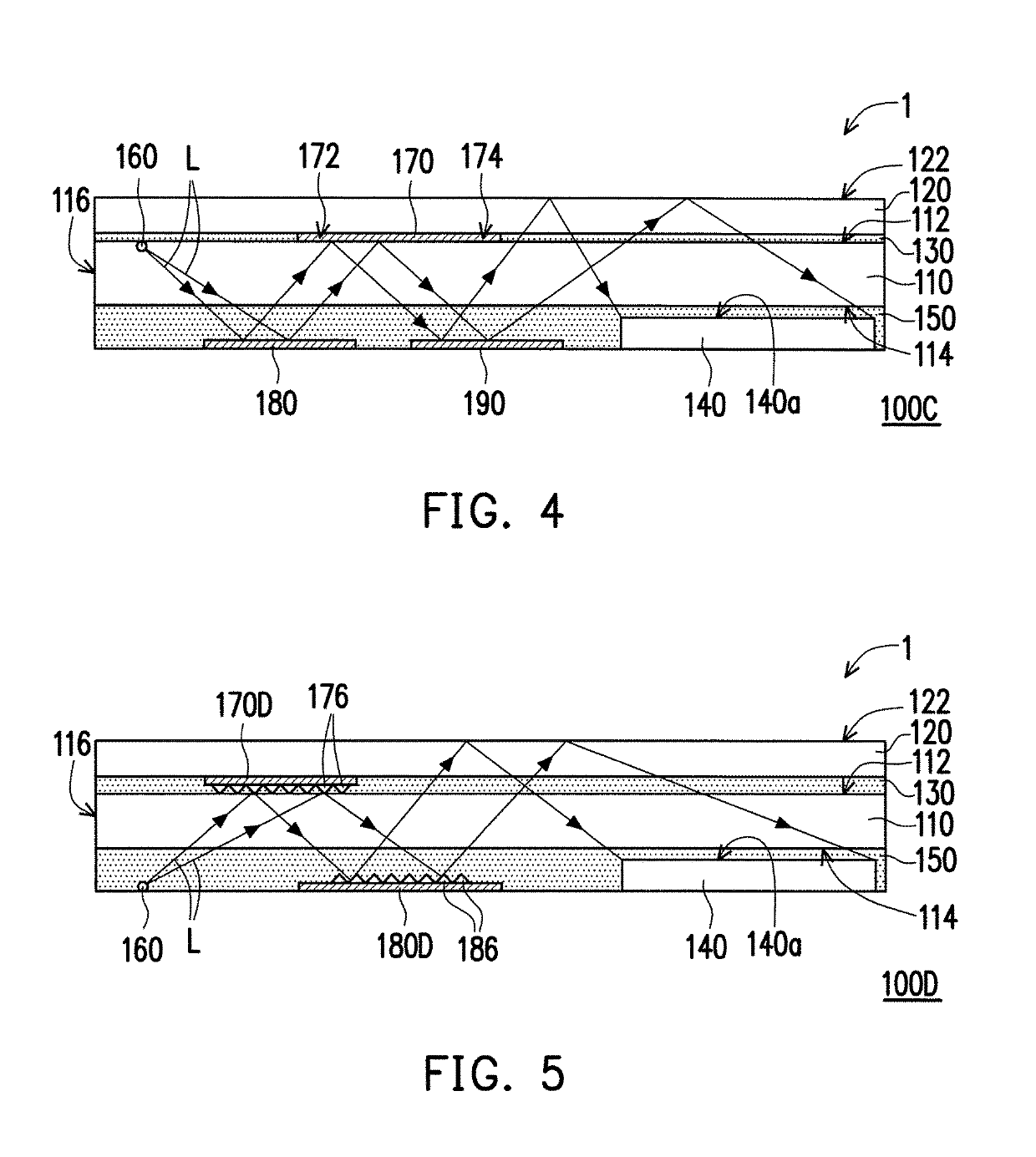
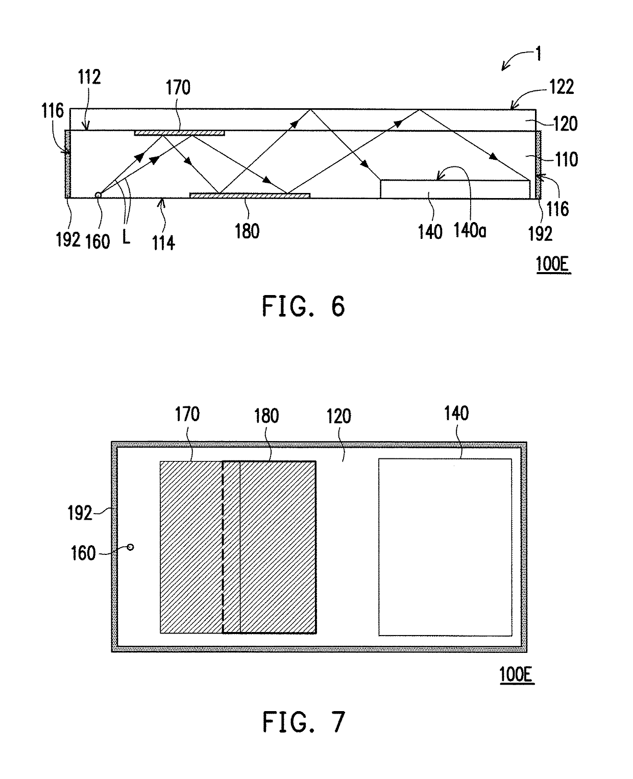
The invention is about an image capturing apparatus with a low cost and good image capturing quality. The apparatus uses a low cost light guide device to replace a part of the optical adhesives required between the transparent device and the image capturing device. This decreases the cost of the apparatus. The light guide device also has a light absorbing layer to improve image capturing quality by absorbing stray light beams incident to the sidewall. The light guide device has two surfaces facing the transparent device, with a first reflecting device on the first surface and a second reflecting device on the second surface. The second surface also has a first light absorbing device to absorb stray light beams transmitted to it. Overall, the invention provides a cost-effective image capturing apparatus with improved image quality.

Problems solved by technology

However, in the conventional technique, the image capturing apparatus of the optical fingerprint identification system requires to use a large amount of optical adhesives with a high material cost, which is of no avail for cost reduction.

Method used


Image

  • Image capturing apparatus
  • Image capturing apparatus
  • Image capturing apparatus

Examples


Embodiment Construction

[0050]The present invention will now be described more fully with reference to the accompanying drawings, in which exemplary embodiments of the invention are shown. The terms used herein such as “above”, “below”, “front”, “back”, “left” and “right” are for the purpose of describing directions in the figures only and are not intended to be limiting of the invention. Moreover, in any of the following embodiments, the same or similar devices are denoted by the same or similar referential numbers.

[0051]FIG. 1 is a cross-sectional view of an image capturing apparatus according to an exemplary embodiment of the invention. Referring to FIG. 1, the image capturing apparatus 100 is located in an environment medium 1. In the present embodiment, the environment medium 1 is, for example, air, though the invention is not limited thereto, and in other embodiments, the image capturing apparatus 100 can also be located in other types of environment medium. The image capturing apparatus 100 is used ...


PUM


Abstract

An image capturing apparatus including a light guide device having a first surface and a second surface opposite to each other, a transparent device disposed on the first surface, an image capturing device disposed on the second surface, a first optical adhesive, a second optical adhesive and a light source is provided. The first optical adhesive is disposed between the transparent device and the first surface. The transparent device is connected to the first surface through the first optical adhesive. The second optical adhesive is disposed between the second surface and the image capturing device. The image capturing device is connected to the second surface through the second optical adhesive. The light source is adapted to emit a light beam. The light beam passed through the light guide device is transmitted toward the transparent device and totally reflected by an interface between the transparent device and an environment medium.

Description

CROSS-REFERENCE TO RELATED APPLICATION[0001]This application claims the priority benefits of U.S. provisional application Ser. No. 62 / 371,230, filed on Aug. 5, 2016, U.S. provisional application Ser. No. 62 / 413,974, filed on Oct. 27, 2016, and China application serial no. 201720260844.9, filed on Mar. 17, 2017. The entirety of each of the above-mentioned patent applications is hereby incorporated by reference herein and made a part of this specification.BACKGROUND OF THE INVENTIONField of the Invention[0002]The invention relates to a photoelectric apparatus, and particularly relates to an image capturing apparatus.Description of Related Art[0003]Types of biometric identification include face, sound, iris, retina, vein and fingerprint identification, etc. Since each person's fingerprints are unique, and the fingerprints are not liable to be changed along with ages or health conditions, fingerprint identification system has become a most popular biometric identification system. Accord...

Claims


Application Information

Patent Timeline
Patent Type & Authority Patents(United States)
IPC IPC(8): F21V8/00H04N5/225G06K9/00
CPCH04N5/2256H04N5/2253G06K9/00H04N5/2254G02B6/0088G06K9/00046G02B6/0055G06V40/1324H04N23/56H04N23/55H04N23/54
Inventor YU, CHIH-CHIANGHUANG, CHENG-JYUNSHEN, PO-HSUNCHEN, PAI-CHICHANG, HAO-HSIANGWU, JEN-CHIEH
Owner GINGY TECH
Learn More