
Frequency nonlinearity calibration in frequency-modulated continuous wave radar

Active Publication Date: 2019-09-24
FUTUREWEI TECH INC
View PDF16 Cites 4 Cited by
  • Summary
  • Abstract
  • Description
  • Claims
  • Application Information

AI Technical Summary

Benefits of technology

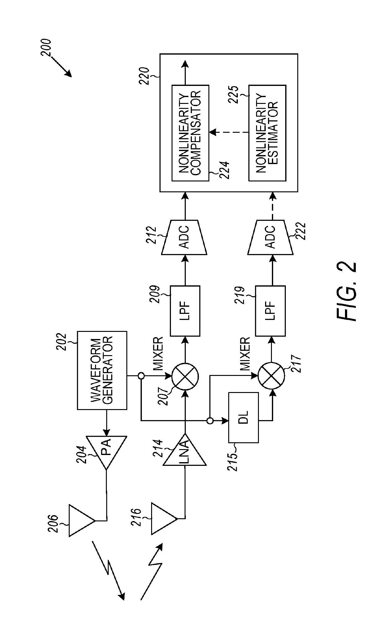
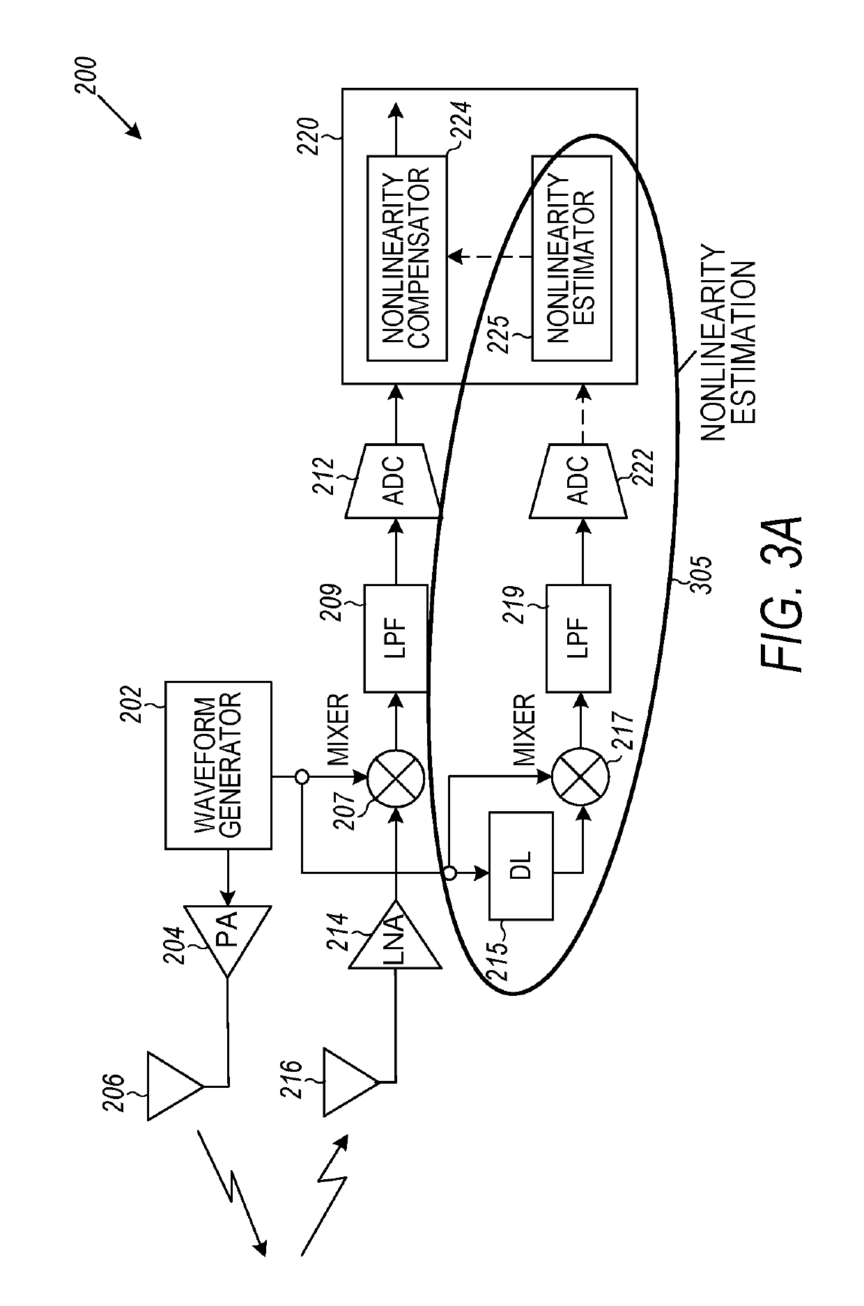
The patent describes a system for frequency-modulated continuous wave radar that can estimate and compensate for nonlinear distortion in the radar signal. The nonlinearity is caused by the waveform generator used to generate the radar signal. The system uses a mixer to combine the radar signal with a return signal from an object, and an analog-to-digital converter to convert the combined signal to a digital form. The system then processes the digital signals to detect objects and perform other functions associated with detection. The system can adjust the nonlinearity estimate to compensate for the nonlinearity and improve radar performance.

Problems solved by technology

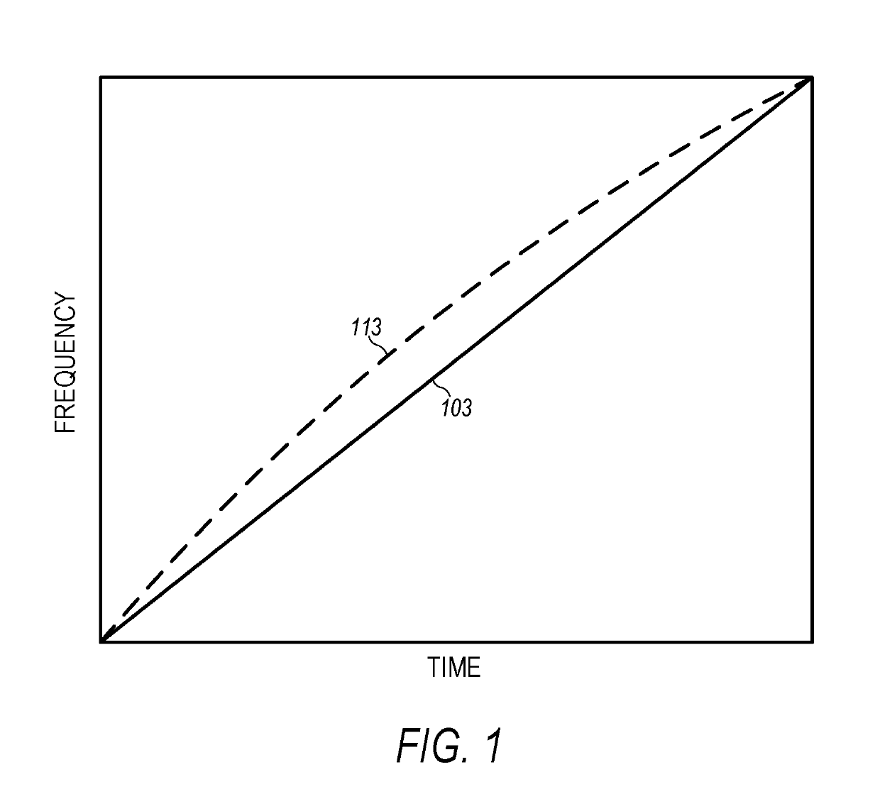
Though the waveform generator is designed and constructed to operate to provide a linear sweep of frequency, such a waveform generator does not generate a perfectly ideal waveform.

Method used


Image

  • Frequency nonlinearity calibration in frequency-modulated continuous wave radar
  • Frequency nonlinearity calibration in frequency-modulated continuous wave radar
  • Frequency nonlinearity calibration in frequency-modulated continuous wave radar

Examples


Embodiment Construction

[0038]In the following description, reference is made to the accompanying drawings that form a part hereof, and in which is shown by way of illustration specific embodiments which may be practiced. These embodiments are described in sufficient detail to enable those skilled in the art to practice the invention, and it is to be understood that other embodiments may be utilized and that structural, logical and electrical changes may be made without departing from the scope of the present invention. The following description of example embodiments is, therefore, not to be taken in a limited sense, and the scope of the present invention is defined by the appended claims.

[0039]The functions or algorithms described herein may be implemented in software in an embodiment. The software may consist of computer executable instructions stored on computer readable media or computer readable storage device such as one or more non-transitory memories or other type of hardware based storage devices...


PUM


Abstract

Various embodiments include methods and systems having a frequency-modulated continuous wave radar operable to compensate a return signal for nonlinearity in the associated radar signal that is transmitted. The radar signal can be mixed with a delayed version of the radar signal such that the mixed signal can be used to generate an estimate of the nonlinearity. The estimate can be used to compensate the return signal from an object that reflects the associated transmitted radar signal. Additional apparatus, systems, and methods can be implemented in a variety of applications.

Description

CROSS-REFERENCE TO RELATED APPLICATIONS[0001]This application is related to co-pending, commonly assigned, U.S. patent application Ser. No. 15 / 493,751, entitled “LEAKAGE SIGNAL CANCELLATION,” filed on Apr. 21, 2017, which is hereby incorporated by reference in its entirety.FIELD OF THE INVENTION[0002]The present disclosure is related to sensing technologies, in particular, to radar-based sensing technologies.BACKGROUND[0003]A radar system transmits a signal and receives its echo. By processing the echo signal, the radar system is able to detect objects, and to estimate the distances, velocities, and directions associated with the objects. Historically, a pulsed radar is used in military applications, where targets of interest are typically far away from the radar system. The pulsed radar emits short pulses, and in the silent period receives the echo signals. The transmitter of the pulsed radar system is turned off before the measurement starts. However, in many civilian applications...

Claims


Application Information

Patent Timeline
IPC IPC(8): G01S7/40G01S7/285G01S7/35G01S13/34G01S13/75
CPCG01S7/40G01S13/34G01S7/352G01S7/4021G01S7/4056G01S7/285G01S2007/4065G01S13/758G01S7/4065
Inventor CHEUNG, RICKY LAP KEIXU, LUZHOUWU, LIXILO, HSING KUOSU, YUAN
Owner FUTUREWEI TECH INC
Learn More