Vehicle framework structure

a vehicle frame and vehicle technology, applied in the direction of vehicle components, superstructure sub-units, roofs, etc., can solve the problems of insufficient effectiveness of cross-members and likely to affect deformation, and achieve the effect of ensuring the stiffness of the vehicle body with respect to an impact load in the vehicle width direction and moderated impact load on the electric power supply componen

Active Publication Date: 2019-09-24
TOYOTA JIDOSHA KK
View PDF23 Cites 1 Cited by
  • Summary
  • Abstract
  • Description
  • Claims
  • Application Information

AI Technical Summary

Benefits of technology

[0005]In consideration of the circumstances described above, the present disclosure provides a vehicle framework structure that may reduce deformation of a vehicle body by an impact load in a vehicle width direction during a side impact of the vehicle.
[0009]In the present aspect, however, the linking cross-member spans between the first side wall portion, which structures a portion of the one cross-members that are adjacent in the vehicle front-rear direction and extends in the vehicle width direction, and the second side wall portion, which structures a portion of the another cross-members, extends in the vehicle width direction and opposes the first side wall portion. The end portion at the one side in the vehicle front-rear direction of the linking cross-member is joined to the first side wall portion of the one cross-member, and the end portion at the other side in the vehicle front-rear direction of the linking cross-member is joined to the second side wall portion of the another cross-member. Therefore, during a side impact of the vehicle in the present aspect, the cross-members that are adjacent in the vehicle front-rear direction may be braced at positions that are closer to neutral axes of bending in the vehicle front-rear direction of the cross-members than in a structure in which cross-members are linked by a linking member disposed at the vehicle lower side of the cross-members. Therefore, even if a cross-member starts to deform to bend in the vehicle front-rear direction due to an impact load in the vehicle width direction, the impact load may be dispersed between the cross-members that are adjacent in the vehicle front-rear direction and the linking cross-member, and bending deformation of the cross-member may be reduced.
[0010]Thus, the vehicle framework structure according to the present aspect may reduce deformation of the vehicle body by an impact load in the vehicle width direction during a side impact of the vehicle.
[0013]Thus, the vehicle framework structure according to the structure described above may improve a degree of certainty with which an impact load in the vehicle width direction during a side impact of the vehicle is dispersed in the vehicle body.
[0017]In the present aspect, however, the cross-sectional shapes of the cross-members seen in the vehicle width direction and the cross-sectional shape(s) of the linking cross-member(s) seen in the vehicle front-rear direction are hat shapes that open to the side thereof at which the floor panel is disposed, and the cross-members and the linking cross-member are joined to the floor panel. Thus, the cross-members and the linking cross-member may respectively form chamber structures with the floor panel. As a result, stiffness of the vehicle body with respect to an impact load in the vehicle width direction may be assured, and effects of the impact load on the electric power supply component may be moderated.
[0018]Thus, the vehicle framework structure according to the structure described above may suppress deformation of the vehicle body by an impact load in the vehicle width direction during a side impact of the vehicle, and the electric power supply component may be disposed in a secure state.

Problems solved by technology

However, bracing a cross-member with a linking member at a position that is distant from a neutral axis of the bending in the vehicle front-rear direction of the cross-member may be insufficiently effective.
Now, if the vehicle body is deformed by an impact load in a vehicle width direction during a side impact of the vehicle, the deformation is likely to also affect the electric power supply component disposed at the vehicle lower side of the floor panel.

Method used


Image

  • Vehicle framework structure
  • Vehicle framework structure
  • Vehicle framework structure

Examples


Embodiment Construction

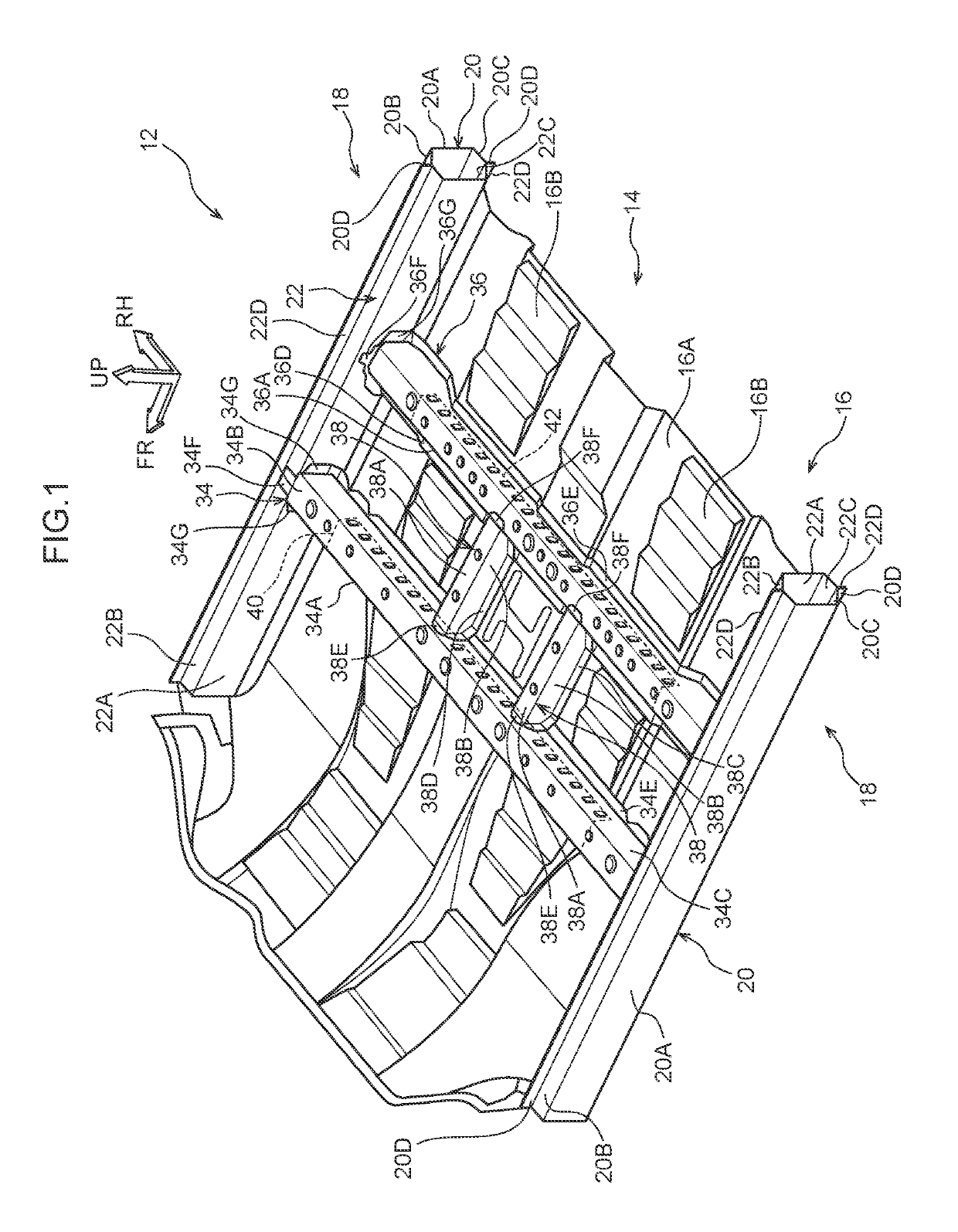
[0023]Herebelow, an exemplary embodiment of the vehicle framework structure according to the present disclosure is described using FIG. 1 to FIG. 3. An arrow FR that is illustrated in the drawings indicates a vehicle front side, an arrow UP indicates a vehicle upper side, and an arrow RH indicates a vehicle width direction right side.

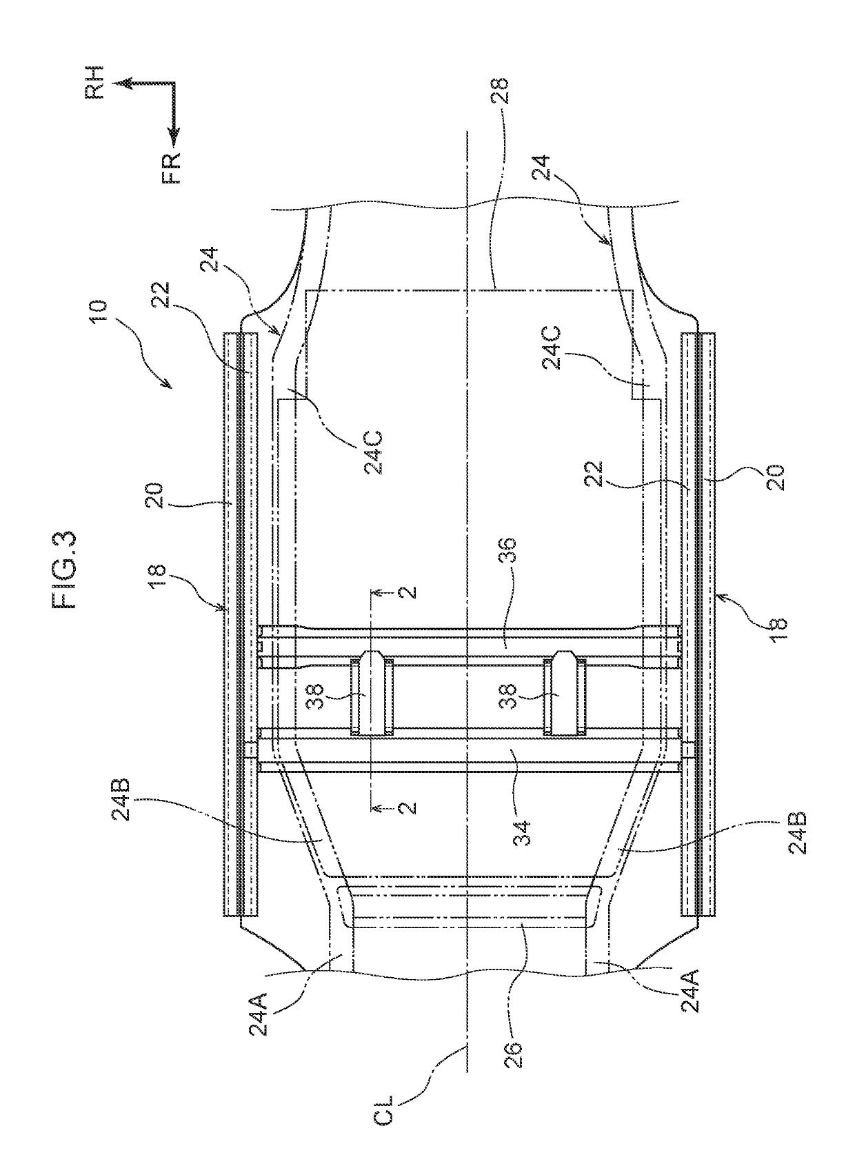
[0024]First, general structures of a vehicle 10 in which the vehicle framework structure according to the exemplary embodiment is employed are described using the drawings. In the exemplary embodiment, the vehicle 10 is basically structured with left-right symmetry. Accordingly, structures in a region at the vehicle width direction right side of the vehicle 10 are principally described below; descriptions of structures in the region at the vehicle width direction left side are omitted.

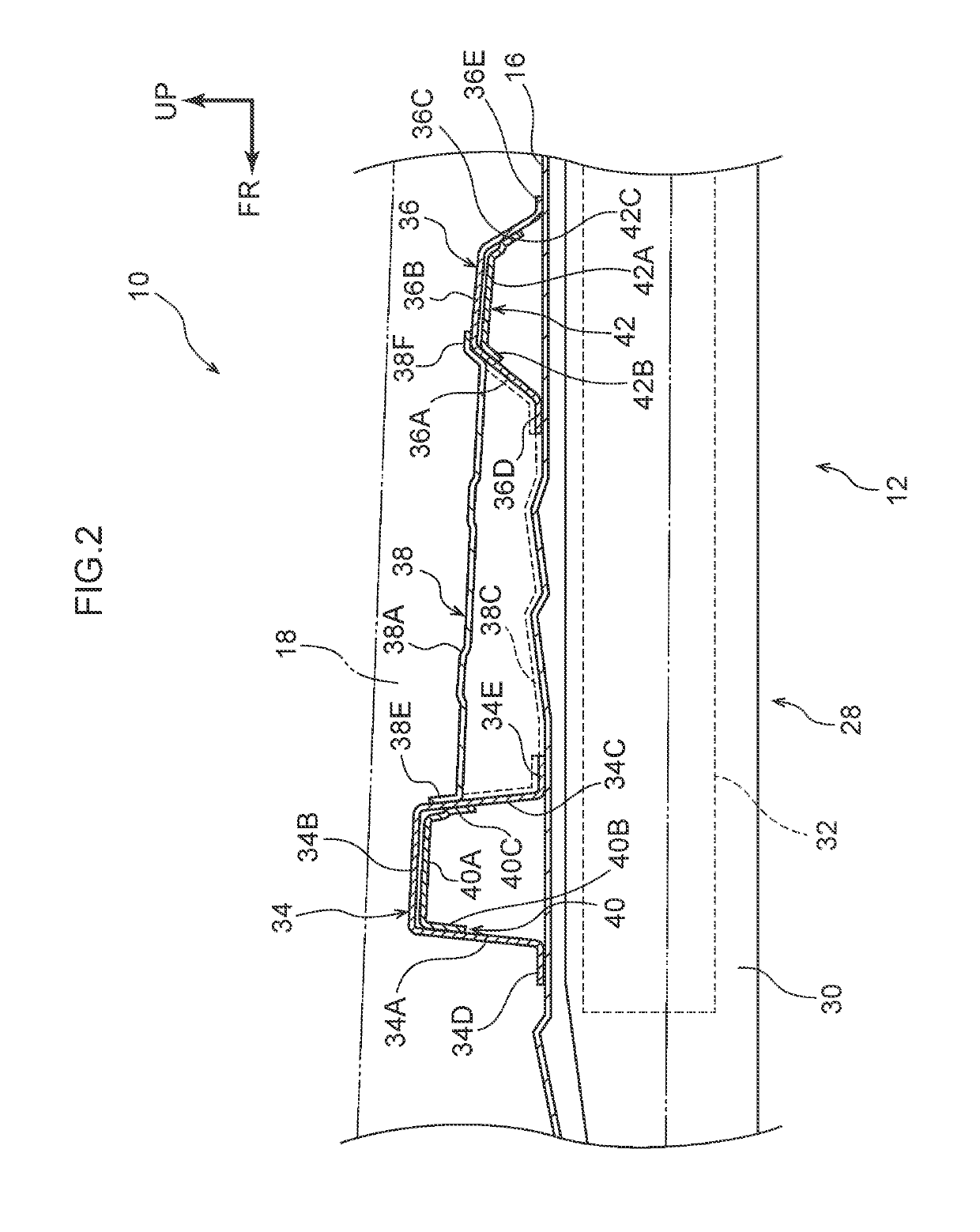
[0025]As illustrated in FIG. 2, the vehicle 10 includes a vehicle body 12, a power unit such as a motor or the like, and a battery pack 28 that serves as an electric power...


PUM


Abstract

A vehicle framework structure includes: a pair of rockers extending in a front-rear direction along outer periphery edge portions of a floor portion; plural cross-members that extend in a width direction and span between the rockers, width direction outer end portions of the cross-members being joined to the respective rockers; and a linking cross-member that spans between a first side wall portion of one cross-member and a second side wall portion of another cross-member, the one cross-member and the another cross-member being adjacent in the front-rear direction, the second side wall portion opposing the first side wall portion in the front-rear direction, an end portion at one side in the front-rear direction of the linking cross-member being joined to the first side wall portion, and an end portion at the other side in the front-rear direction of the linking cross-member being joined to the second side wall portion.

Description

CROSS-REFERENCE TO RELATED APPLICATION[0001]This application is based on and claims priority under 35 USC 119 from Japanese Patent Application No. 2017-020638 filed on Feb. 7, 2017, the disclosure of which is incorporated by reference herein.BACKGROUNDTechnical Field[0002]The present disclosure relates to a vehicle framework structure.Related Art[0003]Chinese Utility Model Registration No. 201347134Y discloses a technology relating to a floor structure of an electric car. In this floor structure for an electric car, a vehicle body is structured with a pair of side members extending in a vehicle front-rear direction, three cross-members spanning between the side members, and a reinforcing member that links the cross-members in the vehicle front-rear direction and extends in the vehicle front-rear direction. Consequently, when an impact load is applied to one of the side members in the vehicle width direction during a side collision of the vehicle (referred to as “a side impact” below...

Claims


Application Information

Patent Timeline
Patent Type & Authority Patents(United States)
IPC IPC(8): B60J7/00B62D25/02B62D21/02B62D25/20B62D21/15
CPCB62D21/02B62D25/2036B62D25/025B62D21/157B62D25/20
Inventor TANABE, DAISUKE
Owner TOYOTA JIDOSHA KK
Why Eureka
Try Eureka