Method for operating a turbo-machine having overload protection and turbo-machine comprising a device for carrying out said method
a technology of overload protection and turbo-machine, which is applied in the direction of machines/engines, liquid fuel engines, instruments, etc., can solve the problems of static methods, not very flexible, and the possibility of directly measuring the torque at the compressor during operation only with considerable effor
- Summary
- Abstract
- Description
- Claims
- Application Information
AI Technical Summary
Benefits of technology
Problems solved by technology
Method used
Image
Examples
example 1
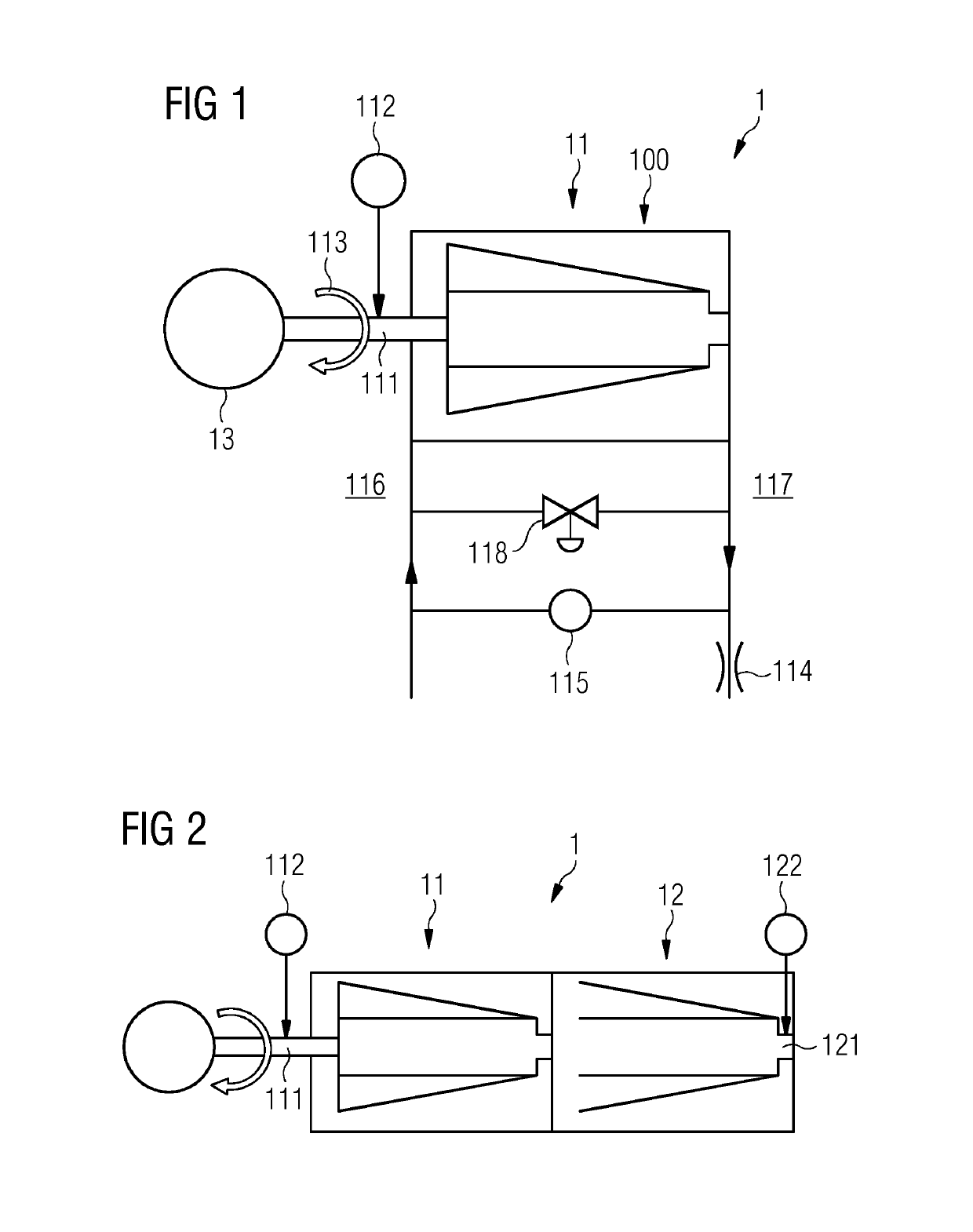
[0035]The turbocompressor 1 is an (axially or radially operated) single-shaft compressor (compressor with only one rotary shaft) having only one compressor stage (FIG. 1). The front side of the compressor stage is indicated by the reference sign 116 and the rear side of the compressor stage by 117.
example 2
[0036]In contrast to example 1, the turbocompressor 1 is a multistage single-shaft compressor (FIG. 2). The turbocompressor 1 has a turbocompressor stage 11 and at least one further turbocompressor stage 12.
[0037]The rotary shaft 111 of the compressor stage 11 and the further rotary shaft 121 of the further compressor stage 12 form a common rotary shaft.
[0038]Arranged at the further compressor stage 12 is a further magnetoelastic torque sensor 122. With the aid of the further torque sensor 122, the further torque is tapped in the region of the further rotary shaft 121.
[0039]The torque sensor 112 and the further torque sensor 122 are operated independently of one another.
example 3
[0040]The turbocompressor 1 is a geared compressor (FIG. 3). The compressor stage 11 and the further compressor stage 12 are connected together via a gear mechanism 14. The rotary shaft 111 is driven via the motor 13. The further rotary shaft 121 is coupled to the rotary shaft 111 via the gear mechanism 14.
[0041]The torque of the rotary shaft 111 is measured via the torque sensor 112 and the further torque of the further rotary shaft 121 is measured via the further rotary torque sensor 122. The fluid to be compressed is introduced into the geared compressor and the compressed fluid is removed from the geared compressor again by the adjustable input control apparatus (ELA) 310 and the adjustable output control apparatus (ALA) 320, respectively.
[0042]Further constituent parts are a volumetric flow rate orifice plate 330 and devices for measuring the pressure differences 340 and 350 at the individual compressor stages 11 and 12.
[0043]FIG. 4 indicates how, on the basis of the measured t...
PUM
| Property | Measurement | Unit |
|---|---|---|
| torsional stress | aaaaa | aaaaa |
| torque | aaaaa | aaaaa |
| volumetric flow rate | aaaaa | aaaaa |
Abstract
Description
Claims
Application Information
 - R&D
- Intellectual Property
- Life Sciences
- Materials
- Tech Scout
- Unparalleled Data Quality
- Higher Quality Content
- 60% Fewer Hallucinations
Browse by: Latest US Patents, China's latest patents, Technical Efficacy Thesaurus, Application Domain, Technology Topic, Popular Technical Reports.
© 2025 PatSnap. All rights reserved.Legal|Privacy policy|Modern Slavery Act Transparency Statement|Sitemap|About US| Contact US: help@patsnap.com


