Catalytic converter unit and exhaust gas catalytic converter

a catalytic converter and catalytic converter technology, applied in the direction of engines, mechanical equipment, machines/engines, etc., can solve the problems of disadvantageous welding of damage to adjacent catalytic converter modules,

Active Publication Date: 2019-09-03
DORING ANDREAS
View PDF14 Cites 0 Cited by
  • Summary
  • Abstract
  • Description
  • Claims
  • Application Information

AI Technical Summary

Benefits of technology

[0005]There is therefore a need for a catalytic converter unit for a catalytic converter, in which catalytic converter modules can be more easily replaced. One aspect of the present invention is based on creating a new type of catalytic converter unit for an exhaust catalytic converter and an exhaust catalytic converter having such a catalytic converter unit.
[0006]According to one aspect of the invention, the catalytic converter modules are positioned with respective first flowed-through ends on a support grating, wherein the second flowed-through ends of the catalytic converter modules are located opposite at a counter-holder. The catalytic converter modules are clamped between the support grating and the counter-holder. The invention allows a simple replacement of catalytic converter modules of a catalytic converter unit without problems and without a risk of damage to adjacent catalytic converter modules.
[0007]According to an advantageous further development, the support grating comprises a plurality of first support braces running parallel to one another and a plurality of second support braces which likewise run parallel to one another and perpendicularly to the first support braces, on which the catalytic converter modules are positioned. Preferentially, a sealing element is positioned between support braces of the support grating running directly parallel to one another, on which directly adjacent catalytic converter modules are positioned, which prevents an exhaust gas flow between the casings of the adjacent catalytic converter modules. Support braces running directly parallel to one another preferentially provide an individual tolerance offset for the respective directly adjacent catalytic converter modules. This configuration of the catalytic converter unit is particularly advantageous. The flow of the exhaust gas through the catalytic converter modules is not negatively affected by the support grating. The sealing element prevents that exhaust gas does not flow through the catalytic converter bodies. The individual tolerance offset makes possible the particularly advantageous integration of the catalytic converter unit in a casing structure of an exhaust gas catalytic converter.
[0009]According to a further advantageous further development, spring elements elastically support the support grating on a casing structure of the exhaust catalytic converter and / or the hold-down brace on the casing structure of the exhaust gas catalytic converter and / or the counter-holder braces on the catalytic converter modules. This elastic support is advantageous for offsetting temperature-related expansions.

Problems solved by technology

In particular when in a catalytic converter unit a catalytic converter module has to be replaced, these welded connections have to be undone for example by disc grinding, as a result of which adjacent catalytic converter modules can be damaged.
Accordingly, connecting adjacent catalytic converter modules by welding is disadvantageous.

Method used


Image

  • Catalytic converter unit and exhaust gas catalytic converter
  • Catalytic converter unit and exhaust gas catalytic converter
  • Catalytic converter unit and exhaust gas catalytic converter

Examples


Embodiment Construction

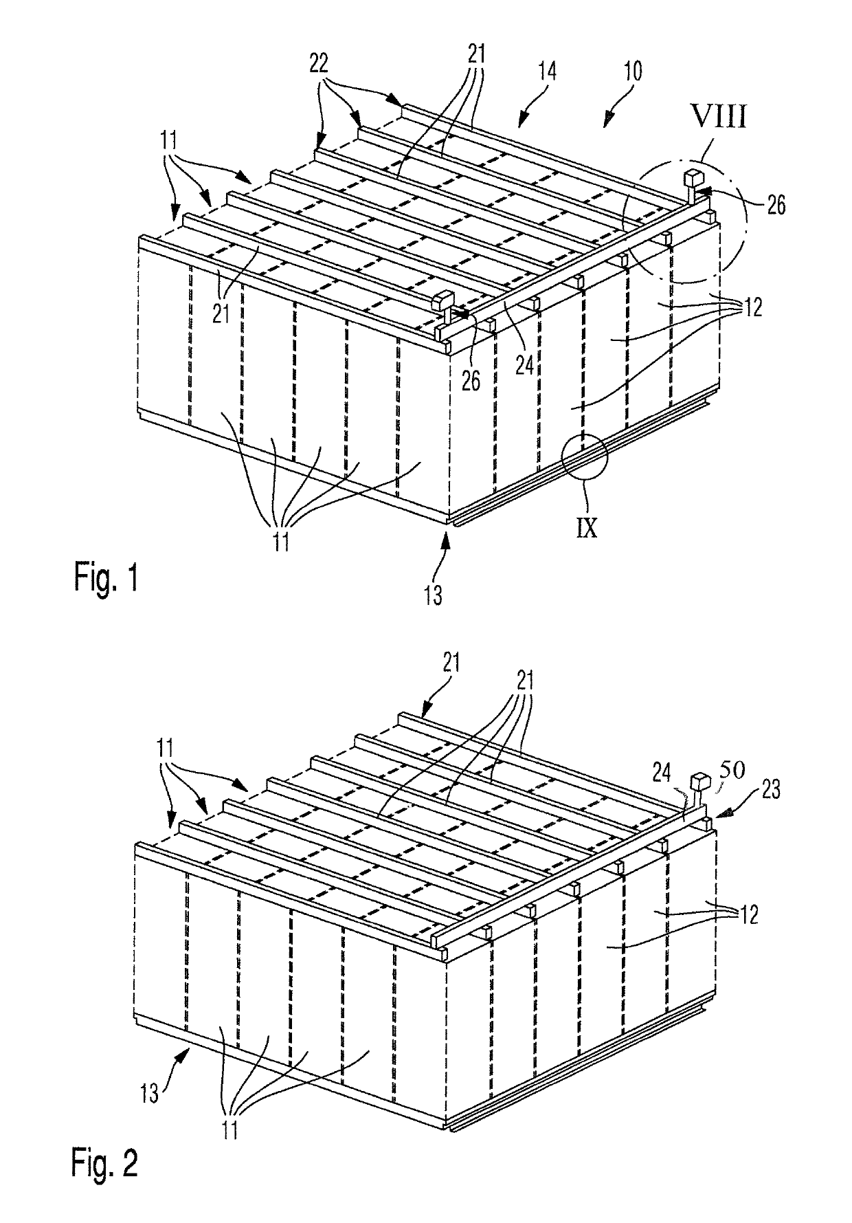
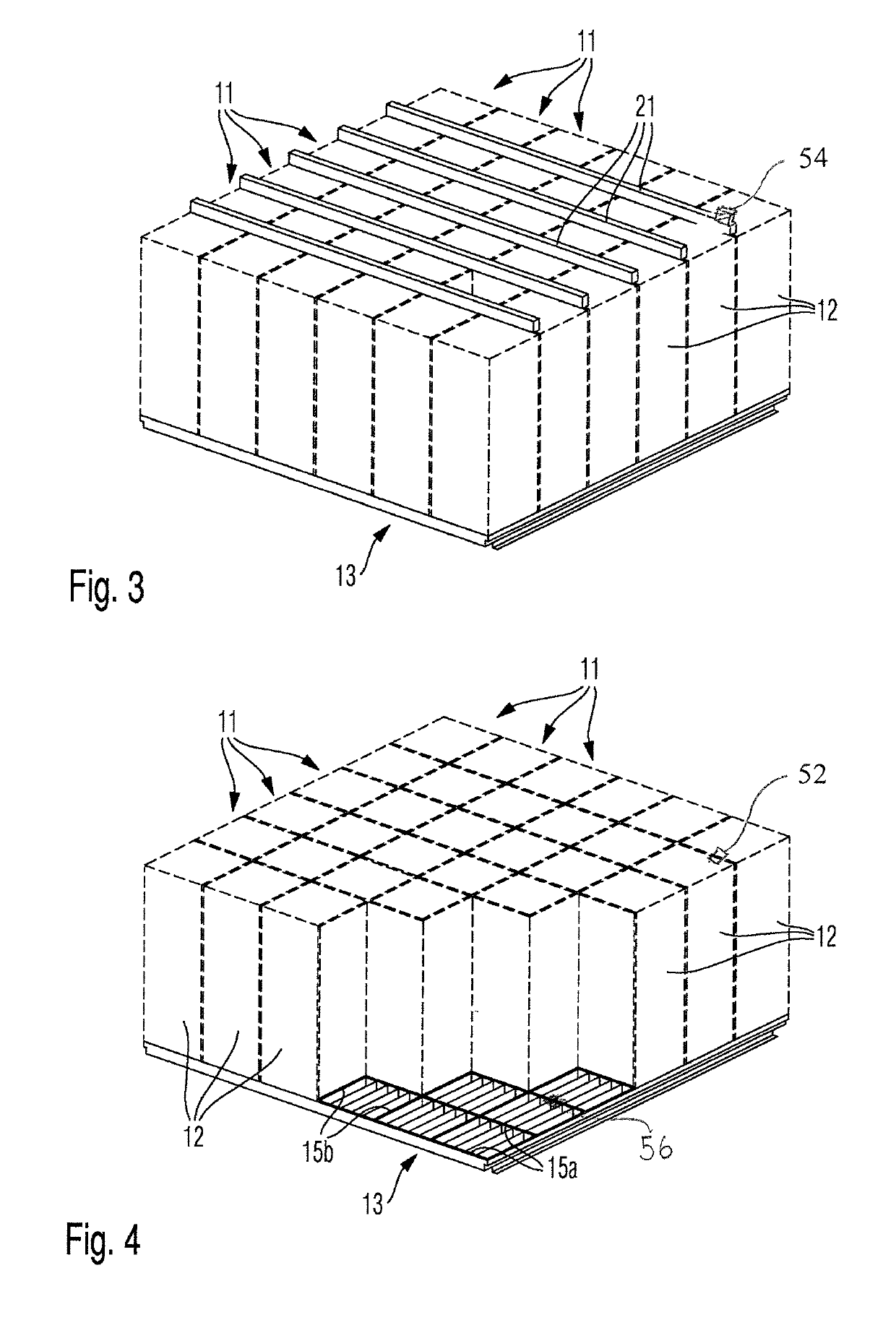
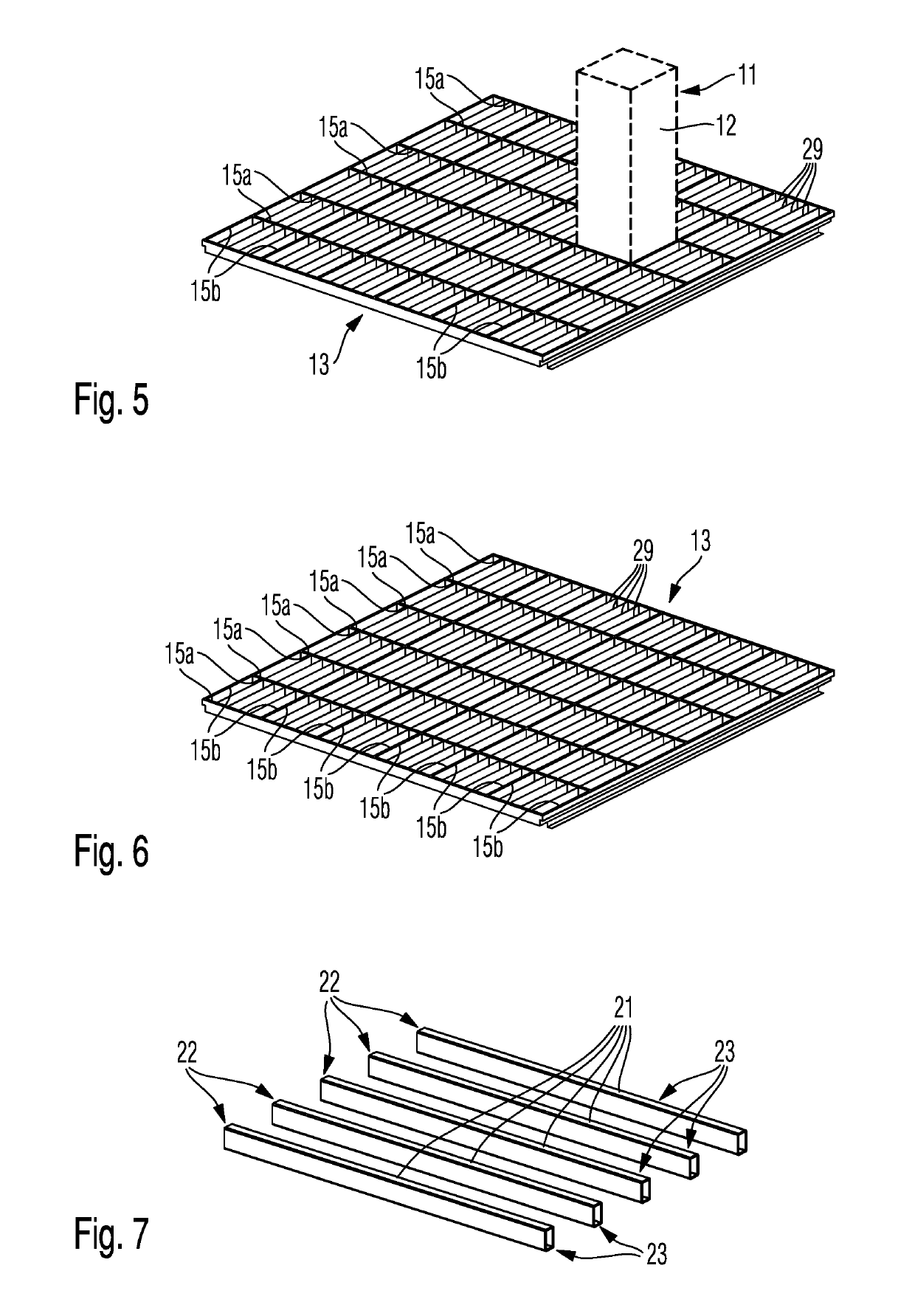
[0021]The invention relates to a catalytic converter unit for an exhaust gas catalytic converter of an internal combustion engine for ship or marine applications and an exhaust gas catalytic converter. In particular, the catalytic converter unit according to the invention is designed as an SCR catalytic converter unit for an SCR exhaust gas catalytic converter of a ship diesel engine. FIGS. 1 to 9 show different views and details of a preferred exemplary embodiment of a catalytic converter unit.

[0022]The catalytic converter unit 10 according to the invention comprises a plurality of catalytic converter modules 11. The catalytic converter modules 11 are positioned array-like in the form of columns and lines directly next to one another. Each catalytic converter module 11 comprises a metallic casing 12, which accommodates a ceramic catalytic converter body, which is not shown. The metallic casings 12 in the shown exemplary embodiment have a rectangular cross section, wherein these cas...


PUM


Abstract

Catalytic converter unit for an exhaust gas catalytic converter, in particular an SCR catalytic converter unit for an SCR catalytic converter of a marine diesel internal combustion engine, with multiple catalytic converter modules. Each catalytic converter module has a ceramic catalytic converter body through which exhaust gas flows and a metallic casing for the ceramic catalytic converter body. The respective ceramic catalytic converter body is received in the respective metallic casing and is surrounded in certain sections by the latter. The catalytic converter modules are positioned with first flowed-through ends on a support grating. A counter-brace is positioned at the opposite second flowed-through ends of the catalytic converter modules, and the catalytic converter modules are clamped between the support grating and the counter-brace.

Description

CROSS REFERENCE TO RELATED APPLICATIONS[0001]This is a U.S. national stage of application No. PCT / EP2016 / 056438, filed on Mar. 23, 2016. Priority is claimed on German Application No. DE102015004007.3 filed Mar. 30, 2015; and German Application No. DE102015219827.8, the content of which are incorporated here by reference.BACKGROUND OF THE INVENTION1. Field of the Invention[0002]The invention relates to a catalytic converter unit and an exhaust gas catalytic converter.2. Description of the Prior Art[0003]A catalytic converter unit for an exhaust gas catalytic converter comprises a plurality of catalytic converter modules. Each catalytic converter module comprises a catalytic converter body through which exhaust gas flows and a metallic casing that is rectangular in cross section for the ceramic catalytic converter body, wherein the casing is also called canning. The casing of the respective catalytic converter module accommodates the respective catalytic converter body and surrounds t...

Claims


Application Information

Patent Timeline
Patent Type & Authority Patents(United States)
IPC IPC(8): F01N13/18F01N3/28F01N3/20F01N13/00
CPCF01N13/18F01N3/2066F01N3/2842F01N13/1844F01N3/2839F01N13/017F01N2590/02Y02T10/24F01N2330/06F01N2450/30Y02T10/12
Inventor DÖRING, ANDREASFABER, MARTINLOSHER, RICHARDNANA, FRANCISDORING, ANDREAS
Owner DORING ANDREAS
Why Eureka
Try Eureka