
Three-dimensional studio system

a studio system and three-dimensional technology, applied in the field of three-dimensional, can solve the problems of difficult to set all elements of the 3d studio, high-quality 3d image of the subject requires a lot of time and effort, and achieve the effect of saving time and effort and easy setting

Active Publication Date: 2019-08-27
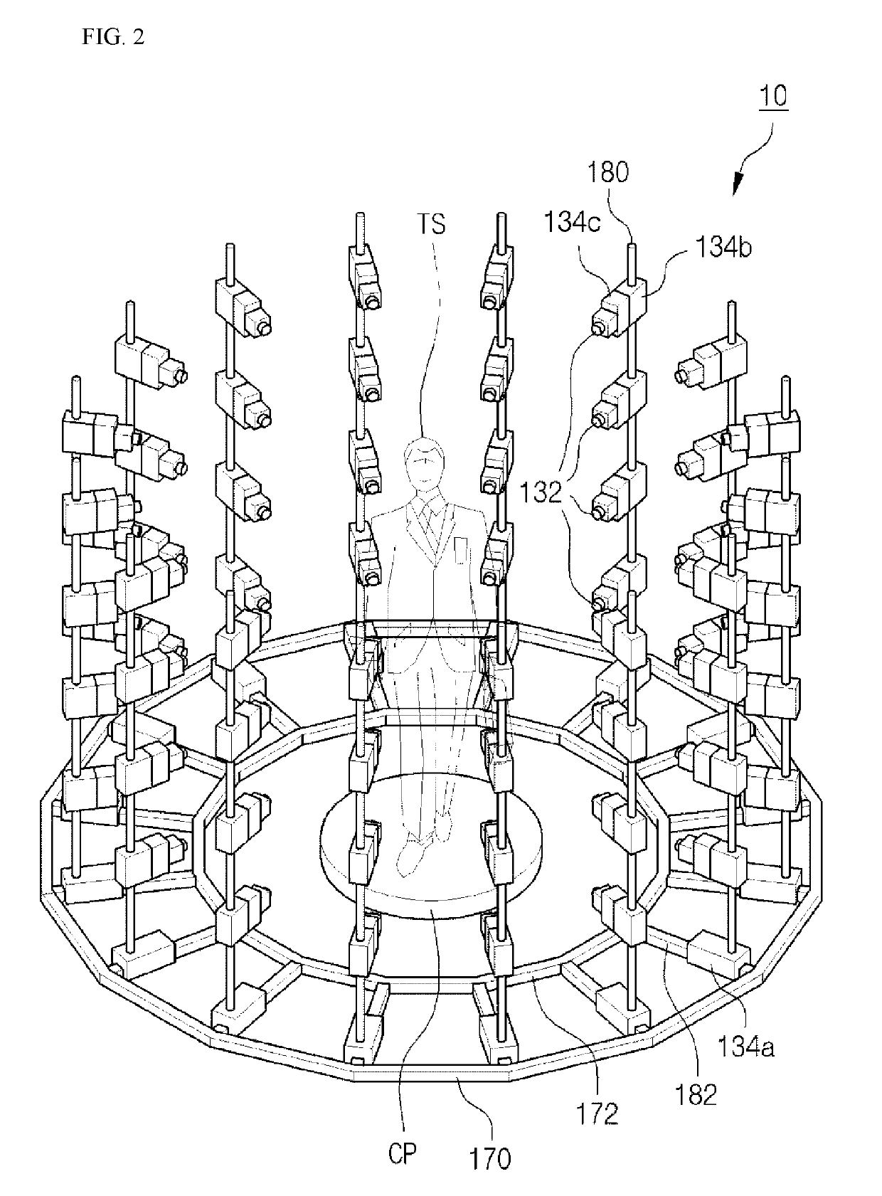
KIM JE HYUNG
View PDF16 Cites 0 Cited by
  • Summary
  • Abstract
  • Description
  • Claims
  • Application Information

AI Technical Summary

Benefits of technology

[0020]According to the embodiment, since a photographing environment may be easily set by sensing a subject, it is possible to save the time and effort required for setting a photographing environment for 3D photographing.
[0021]Also, according to the embodiment, by sensing the various characteristics of a subject, control of a camera and control of camera driving may be controlled to an optimal state for 3D-photographing of the subject.
[0022]Further, according to the embodiment, since camera setting data for controlling a camera and driving setting data for adjusting the position and direction of the camera are stored to have a correlation with a sensing signal, it is possible to control a photographing environment for 3D-photographing of a subject, by using optimal data corresponding to a result of sensing the subject.
[0023]Moreover, according to the embodiment, as a sensing signal and data are stored in a database to have a correlation, optimal data for setting a 3D photographing environment may be provided according to a statistical analysis.
[0024]In addition, according to the embodiment, since a background for a subject may be changed in correspondence to a sensing result, an optimal background for the subject may be provided for 3D photographing.

Problems solved by technology

However, it is very difficult to set all elements constituting the 3D studio to have optimum values in consideration of the characteristics of the object.
Further, finding the optimum values of the respective elements of the 3D studio to obtain a high-quality 3D image of the subject requires a lot of time and effort.
In particular, in the case where the subject is changed or the state of the subject such as a pose, a shape, a position or a color is changed, difficulties are caused in that the photographing environment of the 3D studio should be set again in conformity with a changed subject or the changed state of the subject.

Method used


Image

  • Three-dimensional studio system
  • Three-dimensional studio system
  • Three-dimensional studio system

Examples


Embodiment Construction

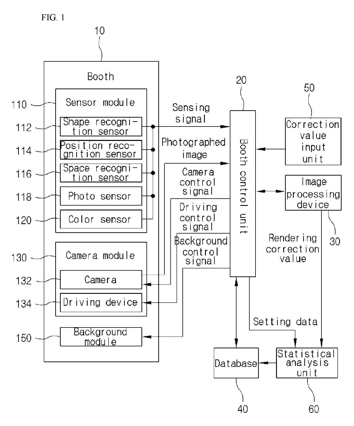
[0035]Hereinafter, embodiments of the present disclosure will be described in detail with reference to the accompanying drawings. The terms used herein and in the claims shall not be construed by being limited to general or dictionary meanings and shall be interpreted based on the meanings and concepts corresponding to technical aspects of the present disclosure.

[0036]Embodiments described herein and configurations illustrated in the drawings are preferred embodiments of the present disclosure, and, because they do not represent all of the technical features of the present disclosure, there may be various equivalents and modifications that can be made thereto at the time of the present application.

[0037]Referring to FIG. 1, a 3D studio system in accordance with an embodiment includes a booth 10, a booth control unit 20, a database 40, a correction value input unit 50 and a statistical analysis unit 60.

[0038]Among the components, the booth control unit 20 is configured to transfer th...


PUM


Abstract

A three-dimensional studio system includes a booth including camera modules each including a camera and a driving device and sensor modules; a database configured to store camera setting data and driving setting data; a booth control unit configured to transfer a photographed image of the camera to an external image processing device, and provide a camera control signal and a driving control signal to the camera and the driving device, respectively; and a statistical analysis unit configured to back up the camera setting data and the driving setting data in the database by reflecting a rendering correction value.

Description

TECHNICAL FIELD[0001]Various embodiments generally relate to a three-dimensional (hereinafter, referred to as “3D”) studio system, and, more particularly, to a 3D studio system which controls a camera and a background installed in a booth for three-dimensionally photographing a subject.BACKGROUND ART[0002]Recently, as a 3D printer is developed and distributed, the necessity and use of a 3D image for a real object such as an article or a person are increasing.[0003]A high-quality 3D image for a real object may be obtained by 3D photographing using a 3D studio.[0004]In the 3D studio, there are installed a plurality of cameras which are disposed by being dispersed around a subject, a plurality of illumination devices for illuminating the subject and a background which is used in photographing the subject.[0005]In the 3D studio, in order for 3D-photographing the subject to obtain a high-quality 3D image, each camera should be set to a different setting value for photographing in conform...

Claims


Application Information

Patent Timeline
Patent Type & Authority Patents(United States)
IPC IPC(8): H04N9/04G01B11/245H04N5/247H04N5/222H04N5/232H04N13/20
CPCH04N5/222G01B11/245G01B2210/52H04N13/20H04N23/60H04N23/90H04N23/698H04N23/66H04N23/951H04N23/6845
Inventor KIM, JE HYUNG
Owner KIM JE HYUNG
Learn More