
Image processing apparatus, image processing method, and program for identifying cells of blood vessel wall

a blood vessel wall and image processing technology, applied in the field of image processing apparatus, image processing method, and program therefor, can solve the problems of reducing the resolution of an slo image of a retina, difficult to observe a blood vessel wall and detect a wall boundary in some cases, and achieve the effect of simple and accurate measurement of the distribution of cells

Inactive Publication Date: 2019-08-20
CANON KK
View PDF22 Cites 0 Cited by
  • Summary
  • Abstract
  • Description
  • Claims
  • Application Information

AI Technical Summary

Benefits of technology

[0024]According to the present invention, it is possible to simply and accurately measure the distribution of the cells that form the blood vessel wall of the eye.
[0025]Further features of the present invention will become apparent from the following description of exemplary embodiments with reference to the attached drawings.

Problems solved by technology

However, along with the increase in the beam diameter of the measuring light, an S / N ratio and the resolution of an SLO image of a retina decrease due to an aberration of an eye to be inspected when the SLO image is acquired.
However, in a confocal image obtained by imaging the inner layer of the retina, a noise signal is strong due to the influence of light reflected from a nerve fiber layer, and hence it is difficult to observe a blood vessel wall and detect a wall boundary in some cases.
However, when the hypertension remains untreated for a long period, the smooth muscle cell that forms the media undergoes necrosis, and fibrous hypertrophy of the media and the adventitia occurs to increase the wall thickness.
Therefore, the measurement is complicated, and includes a measuring error caused by an operator, which raises a problem of low reproducibility.
However, a technology for automatically measuring the wall thickness and membrane thickness of the retinal vessel and the density of cells that form the wall is not disclosed.
However, a venous wall, or membranes or cells that form an arterial wall and a venous wall cannot be visualized from the image of the adaptive optics fundus camera.

Method used


Image

  • Image processing apparatus, image processing method, and program for identifying cells of blood vessel wall
  • Image processing apparatus, image processing method, and program for identifying cells of blood vessel wall
  • Image processing apparatus, image processing method, and program for identifying cells of blood vessel wall

Examples


first embodiment

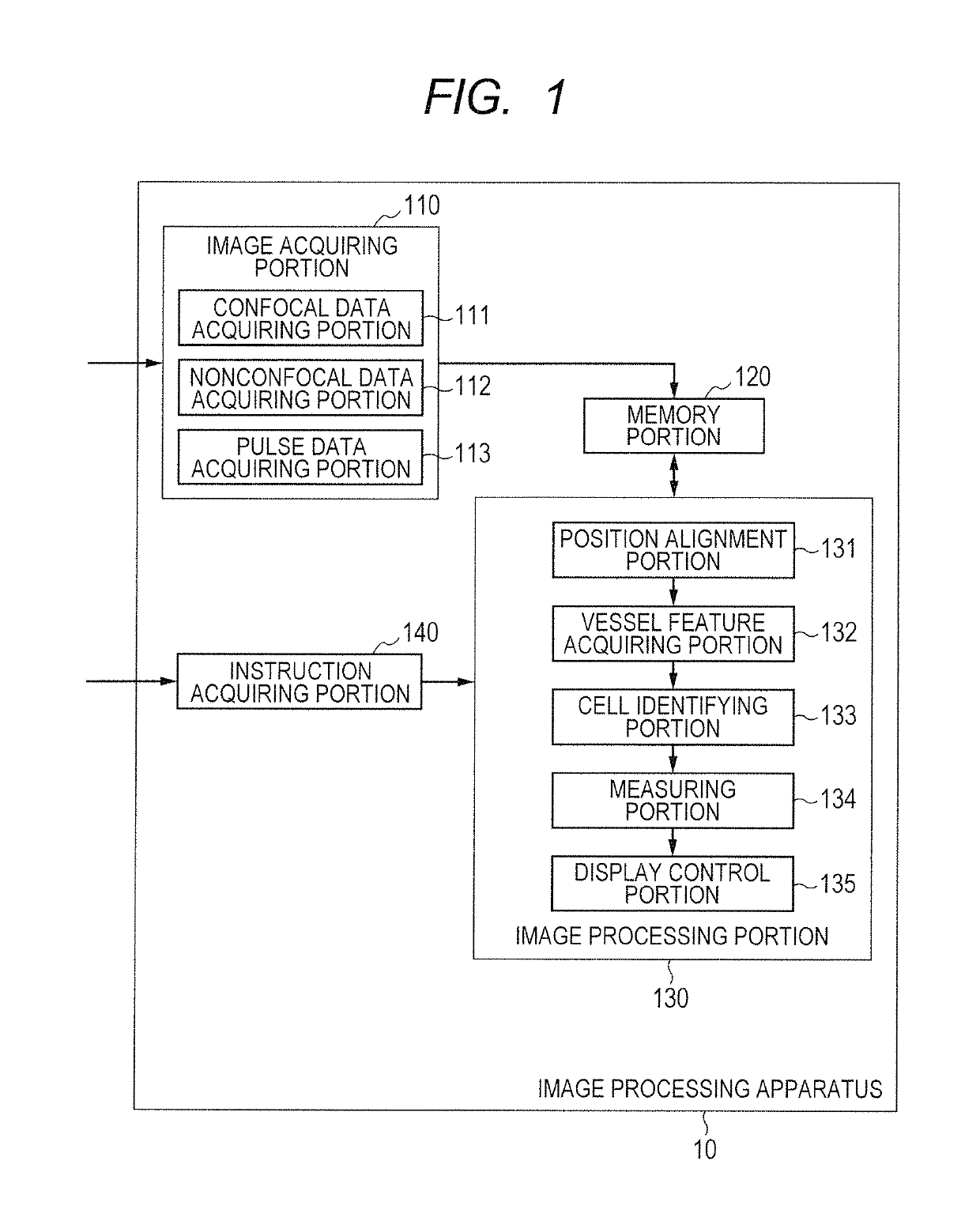
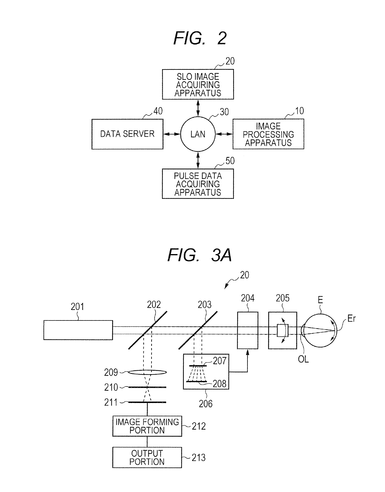
[0054]An image processing apparatus according to a first embodiment of the present invention uses an image obtained by imaging a retinal vessel wall through use of an SLO apparatus configured to simultaneously acquire a confocal image and a nonconfocal image. A brightness distribution along a travel direction of the wall, that is, a vessel travel direction, or an extreme value of a brightness profile is detected from the image. Then, wall cells are detected based on the obtained extreme value, and a distribution thereof is automatically measured.

[0055]Specifically, the retinal vessel wall is imaged through use of the SLO apparatus configured to simultaneously acquire a confocal image and a nonconfocal image. A center line of a retinal vessel (hereinafter referred to also as “blood vessel center line”) is acquired from the obtained nonconfocal image by morphology filter processing. A membrane candidate region that forms the retinal vessel wall is further acquired based on the blood v...


PUM


Abstract

Provided is an image processing apparatus configured to process an image of a fundus of an eye, which is capable of simply and accurately measuring a distribution of cells that form a blood vessel wall of an eye. The image processing apparatus includes: an image acquiring unit configured to acquire an image of an eye; a vessel feature acquiring unit configured to acquire membrane candidate points that form an arbitrary wall of a blood vessel based on the acquired image; and a cell identifying unit configured to identify a cell that forms the wall of the blood vessel based on the membrane candidate points.

Description

TECHNICAL FIELD[0001]The present invention relates to an image processing apparatus, an image processing method, and a program therefor, which are to be used for ophthalmic diagnosis and treatment.BACKGROUND ART[0002]The inspection of an eye has been widely conducted for the purpose of diagnosing and treating lifestyle-related diseases and diseases that are leading causes of blindness in early stages. As an ophthalmic apparatus to be used for the inspection of the eye, there is a scanning laser opthalmoscope (SLO) using a principle of a confocal laser microscope. The scanning laser opthalmoscope is an apparatus configured to perform raster scanning on a fundus of an eye with laser light that is measuring light to obtain a planar image of the fundus based on the intensity of return light of the measuring light, and the image is obtained with high resolution at high speed. Further, in the scanning laser opthalmoscope, the planar image is generated by detecting only light having passed...

Claims


Application Information

Patent Timeline
Patent Type & Authority Patents(United States)
IPC IPC(8): G06K9/00A61B3/12G06T7/12A61B3/00G06T7/00
CPCG06T7/0012A61B3/0025A61B3/1225G06T7/12G06T2207/30101G06T2207/10056G06T2207/30041
Inventor IMAMURA, HIROSHI
Owner CANON KK
Learn More