Machining status display apparatus

a status display and status technology, applied in the direction of program control, instrumentation, testing/monitoring control system, etc., can solve the problems of insufficient stability lobe alone to set appropriate machining conditions, and inability to quickly set machining conditions

Active Publication Date: 2019-08-20
DMG MORI CO LTD
View PDF6 Cites 2 Cited by
  • Summary
  • Abstract
  • Description
  • Claims
  • Application Information

AI Technical Summary

Benefits of technology

[0009]Accordingly, if it is possible to display not only the stability lobe but also information relating to other elements related to machining efficiency, machining costs, and machining accuracy (machining related information) on a screen, the operator can quickly recognize appropriate machining conditions from the displayed information, which is very convenient.
[0018]Thus, with this machining status display apparatus, the stability lobe and the machining related information are displayed in a mutually superimposed manner; therefore, by looking at the diagram and information, the operator can quickly recognize preferable machining conditions which are based on comprehensive consideration of the stability lobe and the other machining related information.
[0020]With this configuration, one or more pieces of information selected from among information relating to a cutting efficiency, information relating to a tool life of the tool to be used, information relating to a total cutting amount the tool to be used is able to cut before reaching the end of its tool life, and information relating to a load acting on a spindle motor, as well as the stability lobe are displayed in a mutually superimposed manner on the display screen of the display device; therefore, by looking at them, the operator can quickly recognize preferable machining conditions which are based on comprehensive consideration of the stability lobe and the selected machining information.
[0027]As described above, in the machining status display apparatus according to the present disclosure, a stability lobe and other machining related information are displayed in a mutually superimposed manner. Therefore, by looking at the diagram and information, the operator can quickly recognize preferable machining conditions which are based on comprehensive consideration of the stability lobe and the other machining related information.

Problems solved by technology

Therefore, in terms of the above-mentioned comprehensive consideration, there is a problem that the stability lobe alone is not necessarily sufficient to set appropriate machining conditions.
On the other hand, appropriate machining conditions have to be set even under such a circumstance; however, to this end, time is needed to sufficiently consider the other elements related to machining efficiency, machining costs, and machining accuracy, and therefore it is not possible to quickly set machining conditions.

Method used


Image

  • Machining status display apparatus
  • Machining status display apparatus
  • Machining status display apparatus

Examples


Embodiment Construction

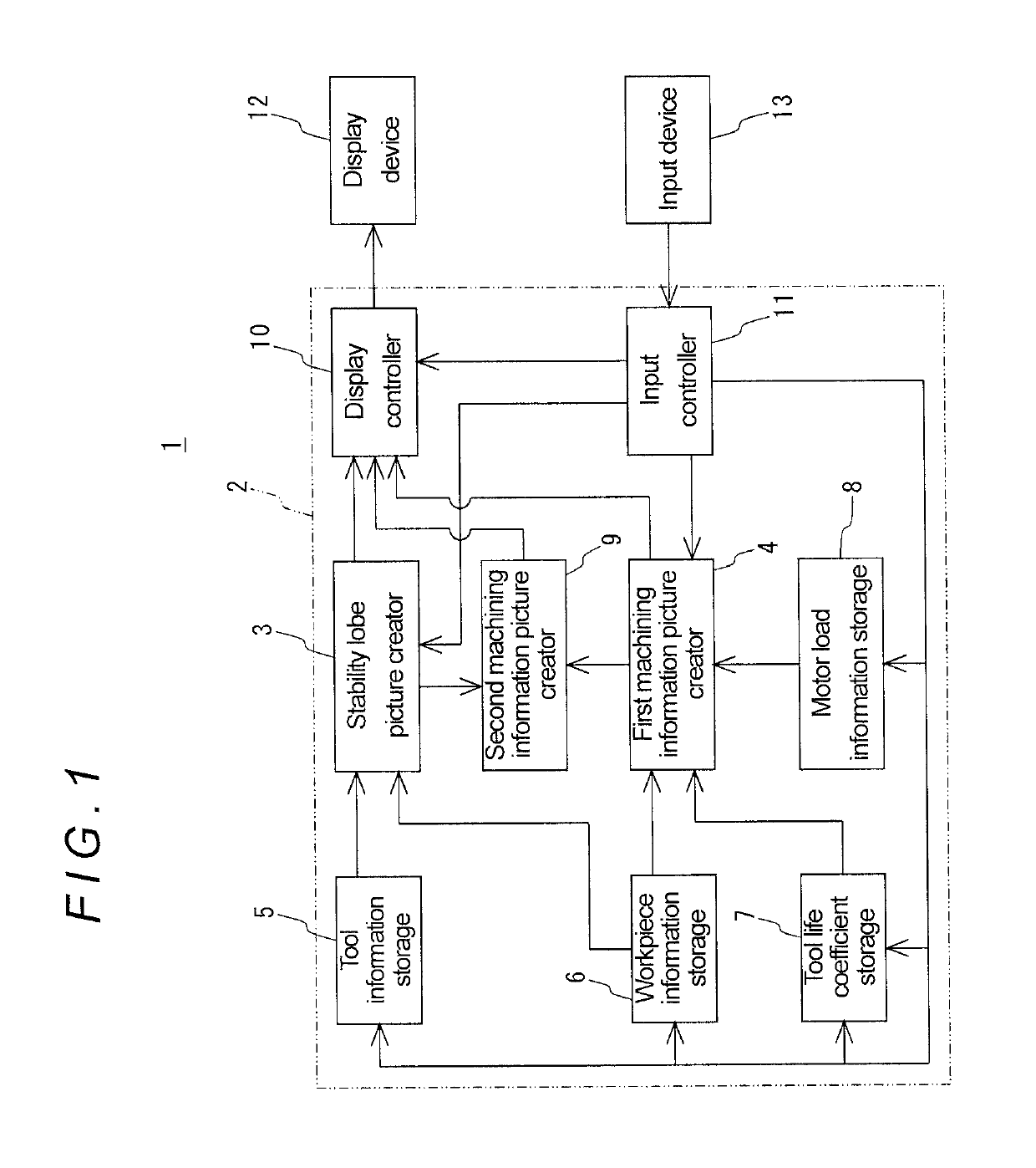
[0050]Hereinafter, a specific embodiment of the present disclosure will be described with reference to the drawings. FIG. 1 is a block diagram showing a machining status display apparatus according to this embodiment.

[0051]As shown in FIG. 1, the machining status display apparatus 1 according to this embodiment includes a computing device 2, a display device 12, and an input device 13; the computing device 2 has a stability lobe picture creator 3, a first machining information picture creator 4, a tool information storage 5, a workpiece information storage 6, a tool life coefficient storage 7, a motor load information storage 8, a second machining information picture creator 9, a display controller 10, and an input controller 11.

[0052]Note that the computing device 2 can be incorporated in a controller of a machine tool, and the display device 12 can be composed of a display provided on an operation panel of the machine tool and the input device 13 can be composed of a keyboard, whi...


PUM


Abstract

A machining status display apparatus includes a display device having a display screen, a stability lobe picture creator creating, based on specifications of a tool to be used, display picture data for displaying a stability lobe as a correlation diagram between a spindle rotation speed and a limit depth of cut of the tool above which regenerative chatter occurs, a first machining information picture creator creating display picture data for displaying machining related information other than regenerative chatter corresponding to set machining conditions, and a display controller displaying the stability lobe and the machining related information with the stability lobe and the machining related information superimposed one on another on the display screen of the display device based on the display picture data created by the stability lobe picture creator and the display picture data created by the first machining information picture creator.

Description

BACKGROUNDField of the Disclosure[0001]The present disclosure relates to an apparatus for displaying a status of machining performed in a machine tool, more particularly, relates to an apparatus for displaying a machining status assumed for machining under predetermined machining conditions.Background of the Disclosure[0002]In the field of machining using a machine tool, machining a workpiece efficiently and reducing machining costs have been pursued, which are permanent issues. At the same time, machining accuracy required in machining becomes higher day by day. Therefore, in machining a workpiece, machining conditions which satisfy required standards have to be set with respect to machining efficiency, machining costs, and machining accuracy.[0003]Accordingly, there has been known a display apparatus that focuses on regenerative chatter among elements related to machining accuracy and is configured to display, on a screen, a stability lobe showing a correlation between a spindle r...

Claims


Application Information

Patent Timeline
Patent Type & Authority Patents(United States)
IPC IPC(8): G05B9/02B23Q17/00G05B19/409B23Q17/09B23Q1/00G05B23/02
CPCG05B23/0272B23Q1/0045B23Q17/007G05B19/409B23Q17/0976B23Q17/0995B23Q17/0952
Inventor KAWAI, KENGOONO, KATSUHIKONISHIKAWA, SHIZUOSAKAMOTO, MASATAKAHIDETA, MORIHIROIIYAMA, KOJI
Owner DMG MORI CO LTD
Why Eureka
Try Eureka