Eureka AIR delivers breakthrough ideas for toughest innovation challenges, trusted by R&D personnel around the world.

Semiconductor-based air conditioning device

a technology of thermoelectric cooling and air conditioning device, which is applied in the direction of machine operation mode, lighting and heating apparatus, heating type, etc., can solve the problems of consuming a lot of energy, heavy and bulky compressor, and inconvenient installation and transportation, so as to improve efficiency and reduce the effect of installation and transportation

Active Publication Date: 2019-08-20
CHEN CHUAN SHENG
View PDF3 Cites 2 Cited by
  • Summary
  • Abstract
  • Description
  • Claims
  • Application Information

AI Technical Summary

Benefits of technology

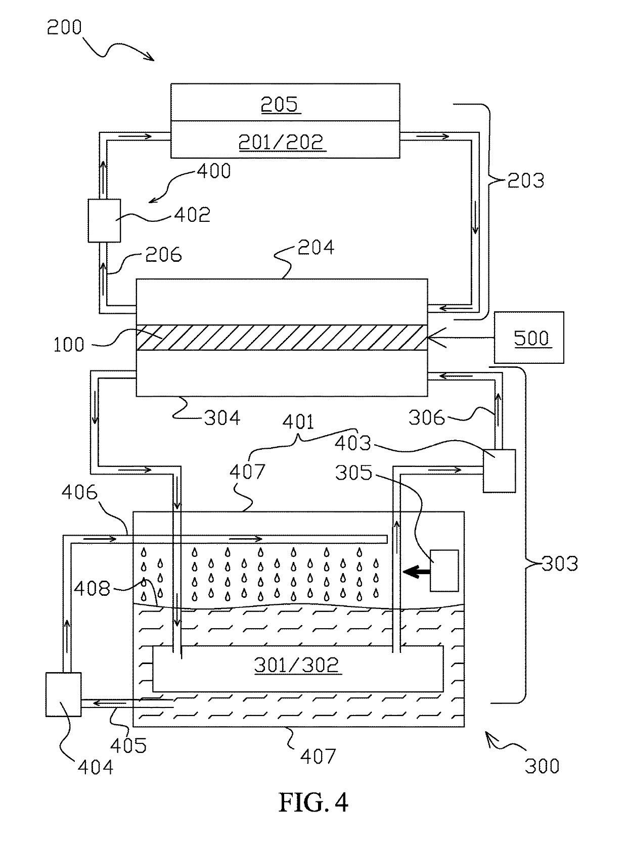
The auxiliary conduction device of the heat dissipating member includes a cooling tank, a tank circulating pump, and two pipes, which all work together to cool the fins and surrounding pipes of the member. The device also includes a fan positioned above the cooling fluid level in the tank, which helps to further dissipate residual heat and prevent it from accumulating and affecting the thermoelectric cooling chip. In summary, the device helps to quickly dissipate residual heat and maintain the cooling process, preventing any negative effects on the overall performance of the device.

Problems solved by technology

The compressor is heavy and bulky, making the installation and transportation very inconvenient.
The compressor also consumes a lot of energy and produces annoying noise that significantly affects the quality of life.
The location of installation is also limited if disturbance to the neighbors by the dripping water and operation noise has to be avoided.
Despite its effectiveness, the device's circulating fluid flow uncontrollably in and out of the cooling pipes 32 and the heat dissipating pipes 42, and therefore its efficiency is not satisfactory compared to where circulating fluid is forced to circulate by electrical pump.
However, it is well known that air cooling is less effective than water cooling.

Method used


Image

  • Semiconductor-based air conditioning device
  • Semiconductor-based air conditioning device
  • Semiconductor-based air conditioning device

Examples


Embodiment Construction

[0015]FIG. 4 is a schematic diagram showing the operation of a semiconductor-based air conditioning device according to an embodiment of the present invention. FIG. 5 is a perspective schematic diagram showing the semiconductor-based air conditioning device. As illustrated, the semiconductor-based air conditioning device mainly include at least a thermoelectric cooling chip 100, 101, a cooling circulating member 200, a heat dissipating member 300, and a power provisioning and temperature controller 500. The thermoelectric cooling chips 100 and 101 are electrically connected to the power provisioning and temperature controller 500. When electricity is introduced, each thermoelectric cooling chip 100 or 101 has a cold production surface and a heat production surface opposite to the cold production surface. The cold production surface is tightly joined to the cooling circulating member 200, and the heat production surface is tightly joined to the heat dissipating member 300. The coolin...


PUM


Abstract

The semiconductor-based air conditioning device includes at least a thermoelectric cooling chip, a cooling circulating member, a heat dissipating member, and a power provisioning and temperature controller. The cooling circulating member is joined to a cold production surface, and the heat dissipating member is joined to a heat production surface, of the thermoelectric cooling chip. Each of the cooling circulating member and the heat dissipating member includes a circulating box, a fan, and an auxiliary conduction device. Each circulating box is covered with fins and surrounding pipes. Each fan is located adjacent to corresponding fins. Each auxiliary conduction device includes an electrical pump. Fluid is stored and circulated in the surrounding pipes of each circulating box. Each electrical pump is configured to pump the fluid in a corresponding circulating box, and fluid is circulated to absorb the cold or heat from the thermoelectric cooling chip.

Description

BACKGROUND OF THE INVENTION(a) Technical Field of the Invention[0001]The present invention generally relates to air conditioning devices and, more particularly, to an air conditioning device utilizing a thermoelectric cooling chip.(b) Description of the Prior Art[0002]Traditional air conditioners and refrigerators utilize compressor and refrigerant to produce the required low temperatures. The use of the compressor has quite a few disadvantages. The compressor is heavy and bulky, making the installation and transportation very inconvenient. The compressor also consumes a lot of energy and produces annoying noise that significantly affects the quality of life. The location of installation is also limited if disturbance to the neighbors by the dripping water and operation noise has to be avoided. Therefore energy-saving air conditioners that are also convenient to move and install with reduced noise are a desirable product.[0003]U.S. Pat. No. 7,251,943 teaches an effective semiconduct...

Claims


Application Information

Patent Timeline
Patent Type & Authority Patents(United States)
IPC IPC(8): F24F5/00F25B21/02
CPCF24F5/0042F25B21/02Y02T10/166F25B2321/0252F25B2321/0212F25B49/00F25B2321/003F25B2321/021Y02T10/12F24F11/70F25B2321/025F25B2321/023
Inventor CHEN, CHUAN-SHENG
Owner CHEN CHUAN SHENG
Why Eureka
Eureka Blog
Learn More